"Calibrating" Charlie using Raspbian for Robots

@cyclicalobsessive

Viz.: Your original posting at:

After reading your treatise above, I decided to “take a whack” at getting some kind of reasonable calibration for Charlie.

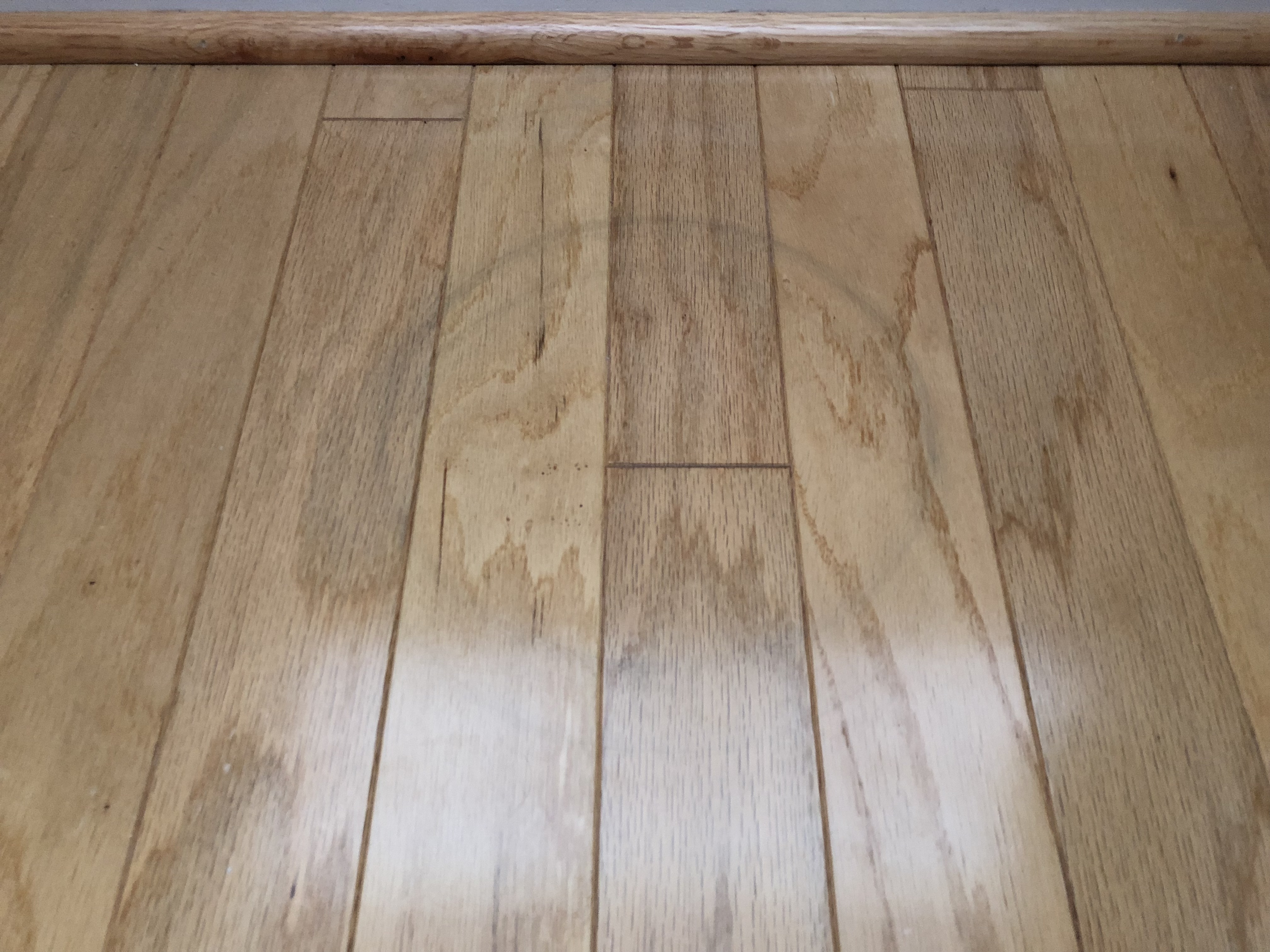
My “test track” is an uneven wooden floor in my living room. Since the GoPiGo wheels are sufficiently “soft” and “sticky”, (get decent traction), I figured a wooden floor would be best.

Unlike Carl, my battery pack is in the back as I have other ideas for the top - like displays or other sensors, etc. I am also still using the “stock” metal ball since I didn’t have a chance to get the nice plastic one like you have.

Objectives:
Using the GoPiGo3 control panel:

  1. Measure out an approximate 2 meter length. (I used my folding carpenter’s ruler) and calibrate Charlie to, (at least reasonably), accurately pace off the two meters. Obviously the closer the better and the more repeatable the better.

  2. Using a thin crack on the floor as a reference mark, calibrate Charlie to make 360’s that return the rear castor to sit on the thin crack, ideally returning to the same spot after five or six revolutions.

Challenges: (Potential sources of error)

  1. The floor is NOT smooth.
    The individual floor-boards, being “utility grade” pine, have developed a significant amount of “bow” across their width, in some cases being a significant fraction of a millimeter, if not more.

  2. Because the floor is not smooth, getting Charlie to drive in a repeatable straight line is not trivial; perhaps not even possible, despite my best efforts. (There is always a certain amount of “yaw”, left or right, of the intended path.)

    • I for one, want to know how you accurately align Carl along a straight line.

  3. I’m still using the metal ball caster instead of the nice plastic one you have.

  4. I’m eyeballing things like “center of robot”, “alignment on the crack” that is my reference line for linear travel, along with the alignment of Charlie’s bumper with the beginning of the folding ruler.

  5. Since I’m using the GoPiGo3 control panel, I only get “two” degrees of freedom - a straight line and a right-hand spin.

Setup:

  1. I had lost one of the two wheel-spacers when I was working with Charlie a while back. I took two out of the new bag of spare kit I bought and replaced the one that was left - and was about 2mm thick, with two that were about 1mm thick. This way I hoped to get reasonably constant and accurate wheel spacing.

  2. I discovered that sensor #3 on the bottom of the line-follower board was as close to the center of the bot as I could eyeball it.

  3. Since I knew MY calibration constants were WAY off, I started with yours as a reference point.

Calibration Methodology:

  1. Straight line:

    • Align Charlie as accurately on the reference line, (crack), as possible.
    • Make a few test runs - some of which yaw to the left, some to the right, trying to minimize the deviation from a straight line. (I never really was able to solve that problem.)
    • Correct the “wheel diameter” by a relatively large jump and repeat until Charlie goes beyond the end of the ruler. (He was always coming up short before.)
    • Using the highly technically calibrated method of “split the difference”, I attempted to zero-in on the end of the ruler.
    • When I reached the point where the error in yaw was significantly greater than the error in line, I called it “good enough” for now. Hopefully I’ll find a better floor and can figure out how to make Charlie run a repeatable line that I can accurately measure.

  2. 360 degree spin:

    • Find a place on the floor, maybe a little bit bigger than Charlie, that’s not unreasonably warped. This really doesn’t exist, but I tried. . . .
    • As close as I could eyeball, I centered Charlie on the crack, with his rear caster sitting directly on it.
    • Using the GoPiGo3 control panel, I executed 360 spins, varying the wheel spacing by relatively large jumps until he began crossing the line - going past 360.
  • Again, using the very heavily computationally intensive method of “split the difference”, I reduced the angular error to the point that after five or six revolutions, the caster would return to its point on the line.

Results:
I’m not going to try to “map the world” with Charlie’s current calibration, but it should dramatically reduce the error in line, and especially the angular error, that I’ve been seeing with Charlie.

My eventual calibration constants became:

  • Wheel Diameter: 64.6
  • Wheel Spacing: 120.5

I didn’t try for anything better than 0.1 increment accuracy since there are still too many things working against me

Stretch Goal:
Find a way to incorporate these updated calibration constants into DexterOS so that my, and my granddaughters, blockly programs make reasonably accurate turns.

Any ideas on how to improve this?

Thanks!

Charlie needs a dedicated play pen with a flat floor and movable walls.

1 Like

Yea, and I need a kick-tush floor planer, (and jet-engine-repair ear protection!), to smooth out a place for him. Since we just spent several teens of thousands of USD to install “street gas” into our house, install radiators, and get a nice wall-mount gas “boiler” to heat this place, (and, damn it all, we’re having one of the warmest winters on record!), I don’t think that will happen any time soon.

Then again, maybe I can make a project out of this with the girls, take it to their apartment with the nice smooth floors, and try to calibrate Charlie there.

Question:
How do you:

  • Center Carl on your straight line for your linear runs?
  • Establish an accurate reference point for the “beginning” and “end” on Carl? (I’m tempted to temporarily install a nail or some other pointy thing on the chassis somewhere.)
  • Keep Carl from drifting right or left?

Stretch Goal:
Find a way to incorporate these updated calibration constants into DexterOS so that my granddaughters, (and my own!), blockly programs make reasonably accurate turns.

I found this laying around - about some kids and a bunch of GoPiGo’s in a classroom having a hoot of a time. Of course, Cleoqc, was The Man of The Hour as far as calibration goes.

Wizard! I’m going to take my calibration constants and try them in Dexter.

Cleoqc also mentioned checking wheel alignment - both parallel to each other and properly aligned with respect to the chassis. Blast it all! I forgot all about that!

Update:
Apparently I didn’t forget. Just to be sure, I re-measured alignment from several different points on each wheel, and they’re dead-on. Just the kind of stuff I get totally OCD about. :wink:

Perhaps four sheets of tag board taped together on the bottom so it will fold up when not in use?

1 Like

A piece of 4x8 Marlite would be even better. (Marlite - the stuff that looks like really thick cardboard with a smooth plastic finish that’s used for walls.) All I have to do is:
(a) Find it
= = = and = = =
(b) Figure out how to get it home using the Russian equivalent of a Hyundai Accent. (It’s called a Solaris over here - they had to upgrade the suspension and increase the ground-clearance!)

I didn’t bother with exactly straight.

For the distance (wheel_dia) I actually drove him across the lines/boards.

Each board is exactly 3 inches, so I used the very back of the caster against a “first floor board” line,
drove 27", and adjusted wheel_dia till the caster ended closest to the far edge of the 9th board.

I just put my eye above the castor and guessed where vertical was. Close enough.

I tried various speeds and found 150 to be “the straightest” and “the most consistent”.

Some start up slip and stopping skid is unavoidable, but there is a speed that will minimize both. (Advanced driving techniques ramp up the speed to avoid slipping, and ramp down to avoid skids.) I also cleaned the dust off the floor to maximize wheel grip and avoid slippage.

BTW, you can see how I picked a center point and starting line for the wheel_base calibration turns.

My calibration routines are in Carl’s git - I was able to adjust the wheel_dia or wheel_base value, line Carl up, then hit return to execute the run, (forward distance, then backed distance), or enter x4 to do fwd-back four times or two times or 10 times to test repeatability when I thought I had a good value.

Wheel Diameter Testing

Wheel Base Testing

Supposedly with the latest easygopigo3.py code there is a “save_robot_constants()” method and a “load_robot_constants()” routine that will keep the wheel dia and base for you, and allow loading it each program you write.

I put the values in a module and run myconfig.setParameters(egpg) before the load/save_robot_constants() methods were available, and still use my module.

AND putting the battery in the center was the key to repeatable turns. The lower friction of the castor on the floor imperfections made a big, big difference - (that’s the wheel_base_width value calibration secret).

1 Like

smooth is good, too smooth is not.

1 Like

Excellent!

Though I am having trouble getting the GoPiGo control panel to “save” my work - clicking on “save and exit” does nothing and “exit” simply throws away what I have done.

Really, heavy tag board can just roll up.

Another Idea is the plastic/rubbery pattern cutting sheet that seamstresses use. It has a non-skid surface and rolls up - even comes with lines and ruled markings.

1 Like

I found large sheets of rather slick, white, Marlite-like wallboard. My concern is that it might be too slippery. There were sheets of a creamier color with a very slight stipple pattern - just enough to give a matte finish. My concern with that is that it’s more beige than white - and I hoped to use it for line-following. A smidge less than $48 with delivery if I get two sheets of the white stuff.

Thew big problem with “roll-up” stuff is that it tends to not lay flat when you un-roll it - unless you let it sit for a day or two. My idea is something that I can fold in half, put out of the way, and then bring it out when the girls want to play.