How to jumper-select configuration/boot options for the Raspberry Pi

Greetings!


One hardware related issue I have been puzzling with is how to make simple configuration changes, at boot-time, without having to either edit the /boot configuration files and/or change SD cards to effect each change.

Or, how to fit more than one O/S on a single SD card, since current SD cards are massively huge compared to the size of these operating system images.
 

For example, I might want to try running Raspbian for Robots with either a 32 bit or 64 bit kernel.  Or, I might want to try running different versions of either Raspbian for Robots, or a new release of the GoPiGo O/S that’s being developed by the good people at Modular Robotics, without having to fiddle with and try to swap-out a tiny and fragile SD card.

Normally, you’d have to either stop what you’re doing, edit something in /boot like the config.txt file, (and run the risk of not editing it back, making yourself CRAZY!!! ), or having to use tweezers - or pliers!! - to remove and replace a tiny and delicate SD card.

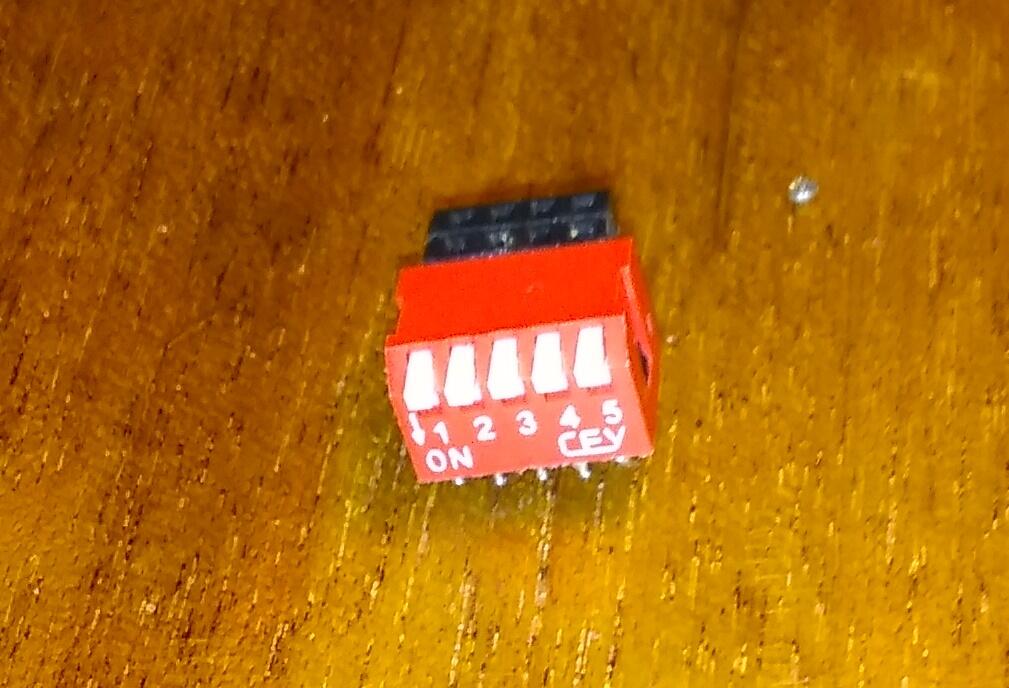
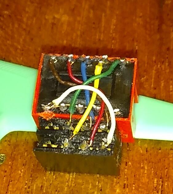
My idea is to develop a way to use little jumper-clips or jumper wires to connect GPIO pins to force a change in configuration at the next boot.

For example, if I want to try a particular version of GoPiGo O/S, (or, Raspbian for Robots), with the experimental 64 bit preemptive kernel, I’d have to edit the config.txt file and either add in, (or comment out), an arm_64bit=1 line.  Not hugely difficult, but it could be easier.

What if I could do this without editing anything?  Perhaps just by connecting two GPIO pins together with a jumper or dip-switch, and then rebooting?

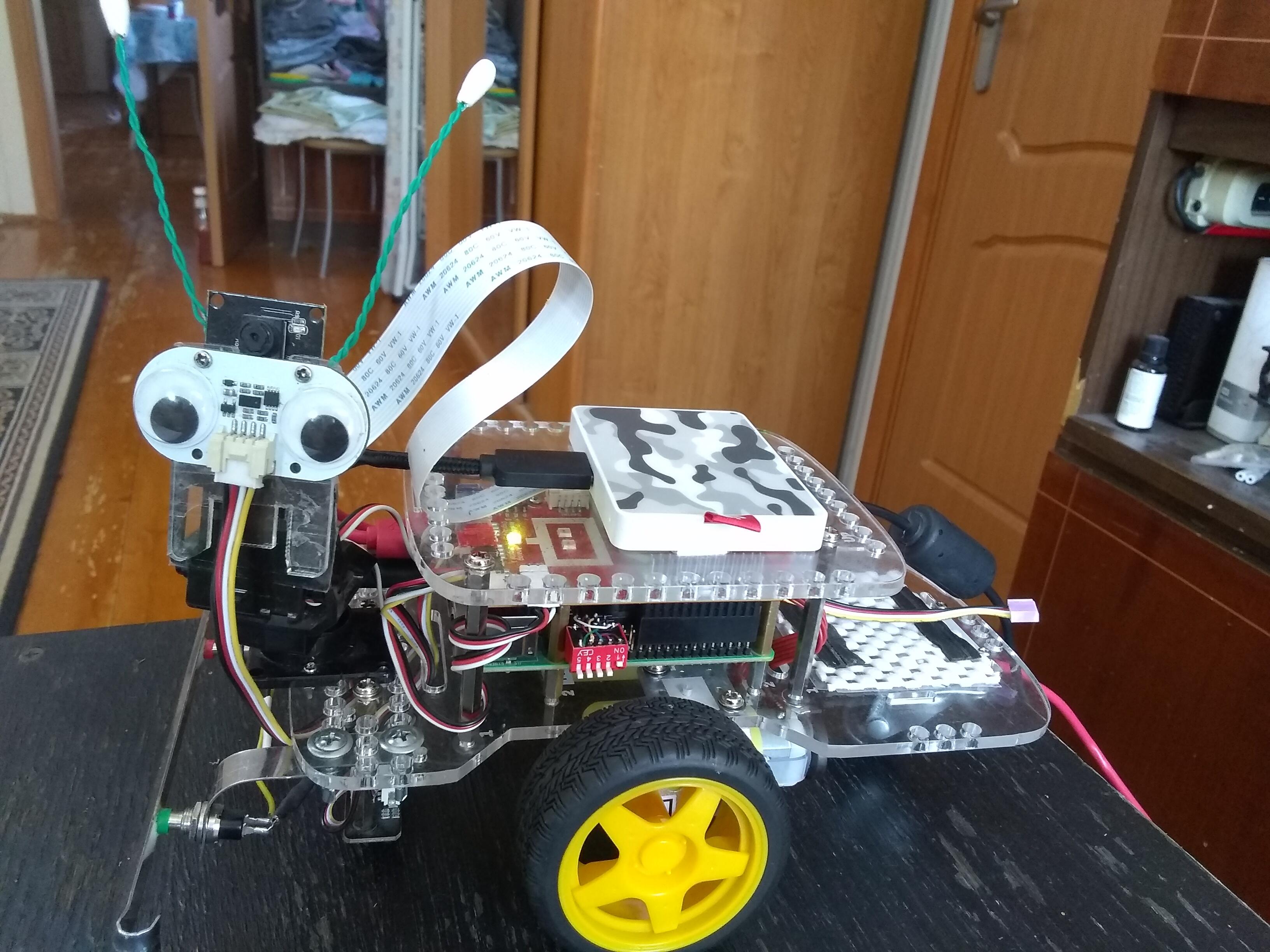
In cases like Charlie’s, where things are already a bit complex, or Carl which is even more complicated, or (God help me!), Derik’s’bot, which is entirely enclosed, trying to fiddle with SD cards and stuff can be complex to the point of disaster.
 

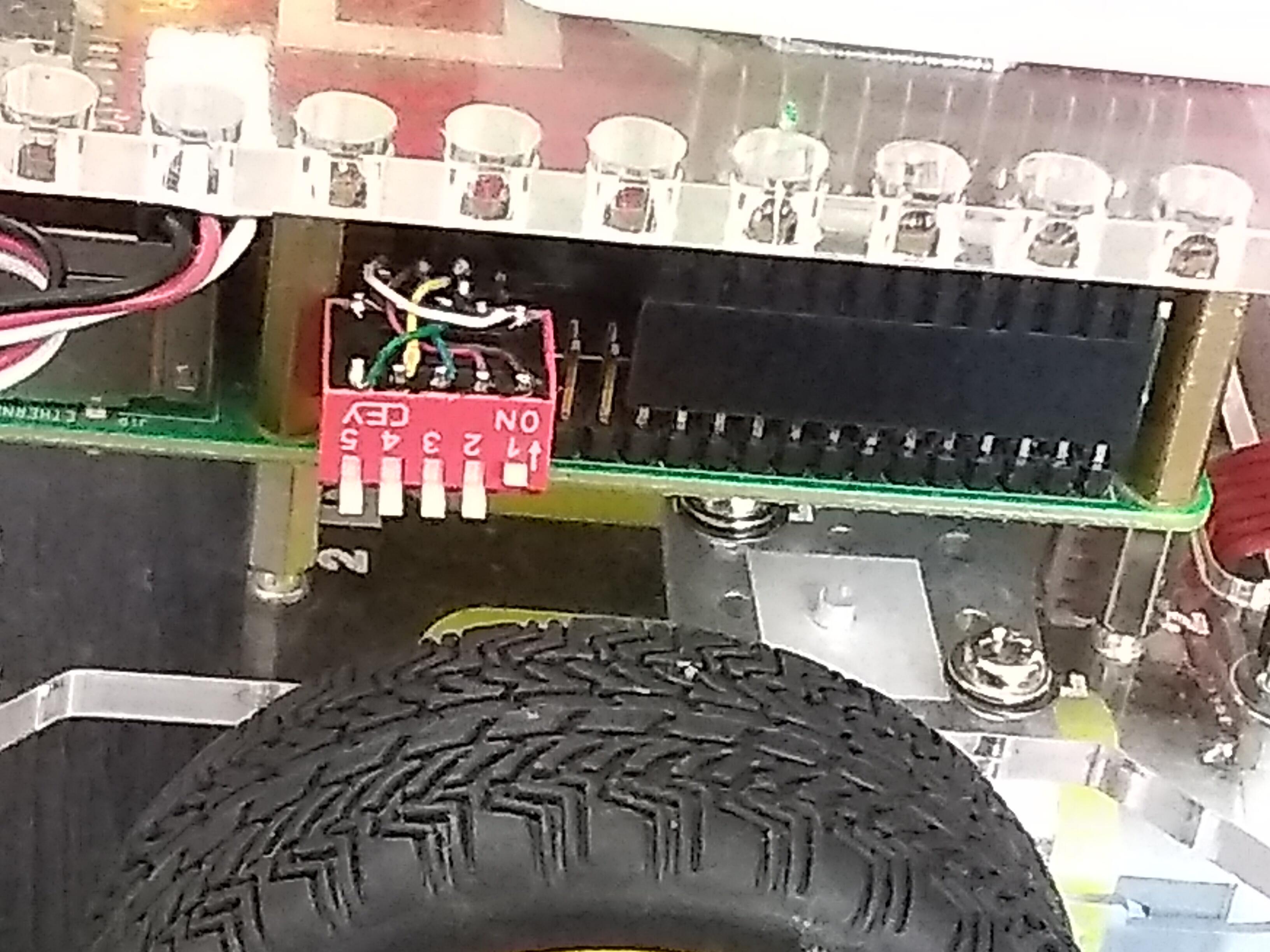
A better way would be to be able to add a jumper or a dip-switch that lets me connect or disconnect individual GPIO pins, (perhaps through a small plug-in header), that brings the selections out to where they can be conveniently manipulated without disassembling the 'bot and potentially damaging things.

All that would need to be done to change something would be to flip, (or un-flip), a particular dip-switch and reboot.


Issue:
In the course of experimenting or testing, I may want to make some kind of configuration change, (i.e.  Trying something with the 64 bit kernel, changing a display option, or even booting a different version of an operating system), that would normally require either editing something in the /boot directory or physically swapping SD cards.  This is especially problematic since swapping SD cards in the GoPiGo can be challenging at best or possibly damage the 'bot or SD card at worst.
 

Concept:
The idea here is that you can have a 'bot, or a Raspberry Pi, with multiple possible fixed configurations simultaneously available, such that one or more combinations of configurations can be selected by hardware jumpers or dip-switches when booting.

Note the emphasis on “when booting” - these are boot-time configuration selections.  Being able to dynamically re-configure the robot at run-time is a totally different topic! :wink:

For example:

  • Two different monitors with two different display resolutions, individually selectable at boot-time.
  • Selecting the 32 or 64 bit kernel at boot time.
  • Selecting one of several different O/S’s to boot at boot time.
    • This is doable, but there are additional considerations, and additional research needs to be done.
  • Select one of several camera configurations.
  • Etc.
     

The requirements I wanted to establish;

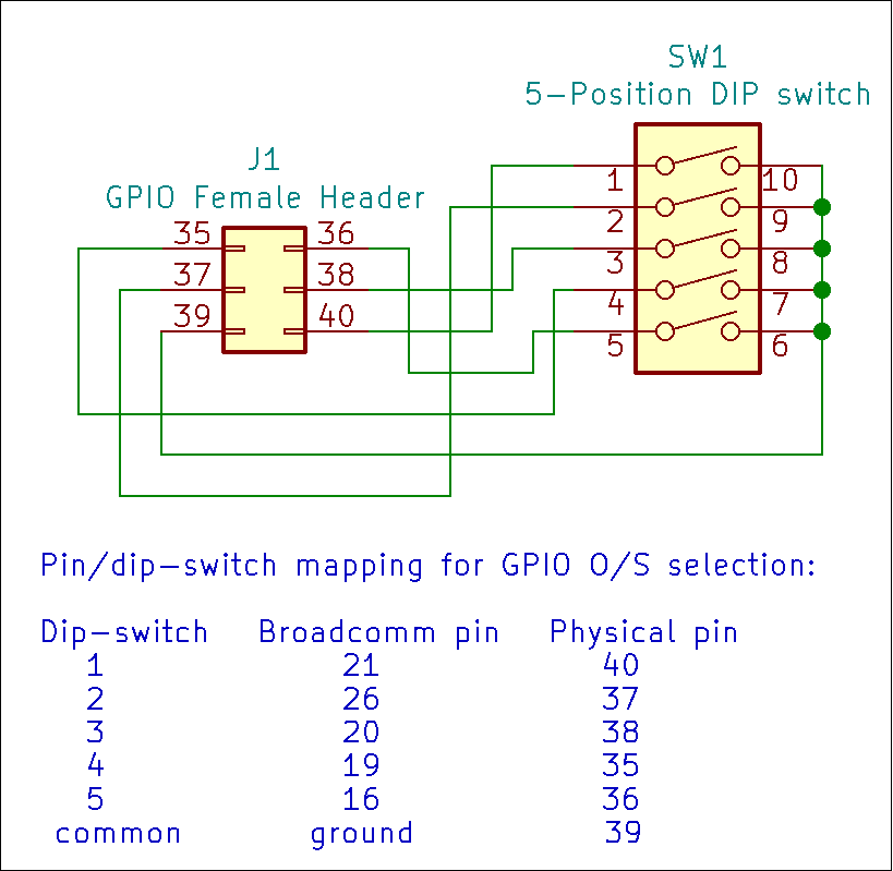
  • Specific configuration changes should be selectable by GPIO pins connected to ground.  (i.e.  via hardware jumpers or dip-switches)
  • Configuration changes should not require removing the SD card.
  • Configuration changes should not require special pre-compiled configuration files like custom firmware overlays or device-tree files that may be difficult to maintain or troubleshoot.
  • Ideally, the alternate configurations should be defined by easily edited files like config.txt or an alternative cmndline.txt
  • Ideally, the configuration should be defined once and then selected by jumpers or dip-switches when rebooting the 'bot.
     

The Setup:
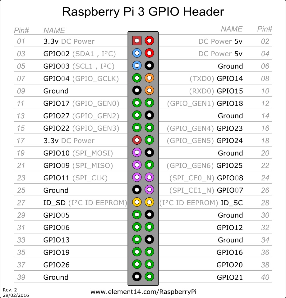
Ref:  The GPIO pin layout.

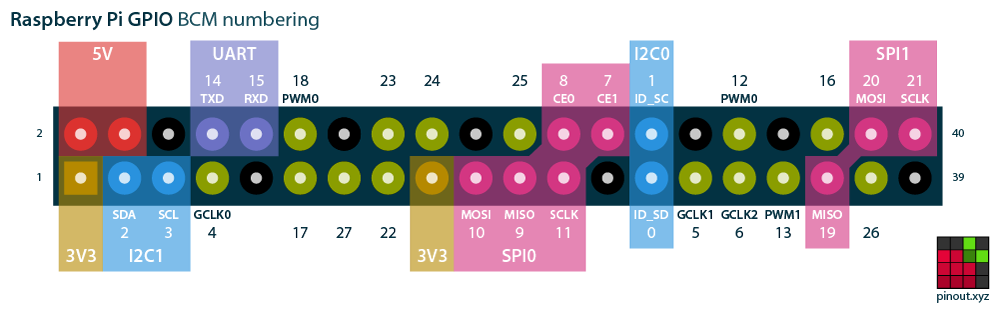
Note: Pin numbers are the Broadcomm internally defined GPIO pin numbers, not the external physical pin number on the header.

  1. I used pins beyond the original 26 pin GPIO set used by the GoPiGo3 controller board, (i.e.  Everything to the right of the vertical “I2C0” block is fair game), because I didn’t remember which of the original 26 pins are or are not being used by the GoPiGo controller board itself.
     
  2. I wanted to use pins that did not have potentially pre-defined uses and might be set by the OS at run-time as they are likely to remain tied to ground if selected.
    • I’m a bit confused by pin “12”, (PWM0), as that’s also assigned to pin “18” in the original 26 pin block too.  Are they shorted together?  I’ll have to investigate this further.
    • Pin “26” might be a better choice as it doesn’t seem to have a pre-defined use, but it was hidden in the “back row” and was difficult to get to.  If I do something with dip-switches and a header, I’ll probably use pin 26 instead of 12.
       
  3. Pin definitions are the Broadcomm pin numbers, (the numbers next to the pins), not the physical pin header numbers, (1-40).
     
  4. For the sake of testing, I selected pins 12 and 16 as they’re easily reachable on the outside edge of the GPIO pins, being the third and fifth pins from the end of the connector.
    • Pin “12” is the fifth pin in.
    • Pin “16” is the third pin in.
    • Each of these pins is immediately adjacent to a convenient ground pin to connect it to if I want to use it.
       

How to do this:

  1. First, select what you want to change, and how to make the change happen:
    • In my case, I wanted to be able to make two selections:
      (a) Select between the 32 and 64 bit kernel image.
      This can be done via a selection in the config.txt file by selecting arm_64bit=11 to select the 64 bit kernel image.
      (b)Select between two different operating system images.
      This can be done by selecting a different, custom, command-line file that selects the partition to boot into.
       
  2. Decide which GPIO hardware pins you want to use:
    • As I mentioned before, I decided to use pins “12” and “16”.
      (a) I use pin “12” to select the kernel image.
      (b) I use pin “16” to select the operating system to boot.
       
  3. Modify the config.txt file to reserve and configure the two GPIO pins.
    • Near the top of the config.txt file, add two lines to assign and configure the GPIO pins you’re going to be using.

In this case “gpio=12=ip.pu” means “set Broadcomm GPIO pin 12 as an input, pulled high to +3 using an internal software pull-up resistor”.  You want the pin to be pulled high so that you can tie it to ground to set the alternate state.

If you don’t specify a specific pull-up/down state for the pin, it can float if disconnected and do weird things.  Specifying a software pull-up and then tying the pin to ground is the safest way as you don’t risk frying delicate GPIO pins.

The second line says the exact same thing, but for pin “16” instead of pin “12”.

  1. Once you’ve set up the pins you want to use, you can test for them later on in the config.txt file by using “gpioxx” pin test statement blocks.
    • For example, later on in the config.txt file, I test for the alternate kernel selection by the following:

This says that if pin “12” is shorted to ground, (pulled low), then select “arm_64bit=1”, otherwise skip it and use the default.

  1. Likewise,

says that if pin “16” is pulled low, execute the custom cmdline.txt file specified to boot a different O/S.

Note that all of these things, including things already in the config.txt and combined together - if you set something more than once, the last setting wins - so these selections should go toward the end of the file - you define default behaviors first, then exceptions toward the end.

For example, my modified config.txt file looks something like this:

====================

Notes about booting an alternate operating system.

This is the “default” cmdline.txt file as-shipped.

(I eliminated the “quiet splash” as I want to see boot-time messages)

To add an additional operating system image, I copied the “rootfs” partition from a working image to a third partition on the SD card I wanted the image to be on.  (Gparted is your friend, it can create additional partitions, AND copy them!)

When I did this, I needed to create a special “cmdline.txt” file that points to the third partition instead of the second one, so I created a “cmdlinep3.txt” file that contains:

Note the difference:

  • The original cmdline.txt file has root=PARTUUID=ca78f9f0-02 - which specifies booting from the second partition.
  • The modified, and renamed cmdline.txt file has root=PARTUUID=ca78f9f0-03 - which specifies booting from the third partition.
  • Also note that the PARTUUID has to be the actual UUID for the disk volume you’re using - if it boots, its the one in the original cmdline.txt file.
     

Additionally, prior to booting the new partition, you have to go to the /etc/fstab for the new partition and make sure both /boot and / (root) specify the correct UUID, (it can be different if copied from somewhere else), and that root specifies the correct partition, in this case “03”.  Failure to do this will result in a system that gets entirely tangled up on itself when it tries to boot.

So far, I can get both operating systems to boot, but the operating system booting from the alternate partition never quite works correctly - and there may be other fixups needed that I have not yet discovered.
 

Summary:

  1. Decide what changes you want to be able to select between.
     
  2. Decide what has to happen to make the changes work.
    • A change in kernel definition?
    • A change in a config.txt parameter?
    • A different cmdline.txt file?
    • Something else?
       
  3. Experiment with the changes, and the commands needed to select them before trying to get fancy.  Test to make sure the changes - and how to select them - actually work.
    • i.e. Does selecting “arm_64bit=1” in the config.txt load the correct 64 bit kernel?
      Hint: Type “uname -a” in a terminal window, and if things like “PREEMPT” and “arm64” show up, you’re golden!
    • i.e. Does selecting a custom cmdline.txt, (by renaming and substituting a new one), boot properly?
    • You need to get all the selections and changes you might want to do working in a “standard” configuration - by editing the config.txt/cmdline.txt files - before trying to get fancy.
       
  4. Once everything is working when done by hand. . .
    Then select the GPIO pins you want to use and configure them.
    • gpio=NN=ip.pu - where “NN” is the pin you want to use.
      You select the pin by shorting it to a “black” (ground) GPIO pin.
       
  5. Then, select the pin and test it in your modified config.txt file
    • Create a section
      [gpioNN=0]
      which selects what to do when the pin is pulled low, (the “alternate” behavior), such as “boot an alternate kernel” by specifying something like arm_64bit=1
    • Viz.:
      [gpioNN=0]
      arm_64bit=1
       
  6. Test, test, test, and continue testing until you get it right.
     

Credits:

  1. Huge credit goes to the people on the Raspberry Pi forums who provided links, advice, (lots of good advice!), and a number of different suggestions on how to do this, both in hardware and software.  If my hardware-centric method doesn’t quite fit your needs, you would do well to look at some of the alternate methods proposed.  All are good and all are worthy of a careful read.
     
  2. Everybody here on the Dexter Industries / Modular Robotics forums.
    It’s people like you who give me the inspiration and, (let’s be honest here), the courage to try something, publish results, and not fear being torn to shreds if it’s not quite ready for prime time.
     
  3. The people at Dexter/Modular Robotics who came up with the idea for a robot like the GoPiGo.  Without that, God Himself only knows what I’d be doing otherwise.
     
  4. Special mention goes to Nicole, (@cleoqc), for being the GoPiGo champion she is, and being an example for all of us.  I for one vote that she change her username to st.cleoqc. She should be sainted! :grin:
     

Notes about booting into the 64 bit kernel:

  1. Theoretically, you could boot into a 64 bit kernel simply by specifying the kernel to boot, in this case the “kernel8.img” kernel.  However, there’s more to this than simply changing kernels.
     
    By default, the Broadcomm SoC, (System on a Chip), that implements the Raspberry Pi is configured internally in a number of ways to behave as a 32 bit system even though it has the potential to run as a full-bore 64 bit system.
     
    In order for the Raspberry Pi to run correctly in a 64 bit environment, several different internal states and registers need to be changed prior to booting the kernel for it to work properly.
     
    The correct way to select “64 bit kernel mode” is to execute the statement arm_64bit=1 within the config.txt file.  This allows the Raspberry Pi SoC to make the needed internal configuration changes and then automatically load and run the “kernel8.img” kernel.

Thanks!

2 Likes
  • GoPiGo3: Unused GPIO Pins of 26 pin connector:
    7:GPIO 4
    24:GPIO 8 SPI_CE0
    11:GPIO 17
    13:GPIO 27

  • GoPiGo3: Unused pins of 40 pin connector:
    27: ID_SD (I2C ID use only)
    28: ID_SC (I2C ID use only)
    29: GPIO5
    30: Gnd
    31: GPIO6
    32: GPIO12
    33: GPIO13
    34: Gnd
    35: GPIO19
    36: GPIO16
    37: GPIO26
    38: GPIO20
    39: Gnd
    40: GPIO21

1 Like

I wanted to specifically avoid pins with “alternate” uses - like my use of pin 12, the “PWM0” pin - because these pins can, and might, have issues with being grounded while the device is running.

Since GPIO pin 12, (physical pin 32) is potentially tied to GPIO pin 18, (physical pin 12) - at least on my chart - I may have to avoid that in favor of GPIO pin 26, (physical pin 37) as it is not pre-defined as anything.  The only reason I didn’t do that in my original research was that pin 26 was buried in the back row while pin 12 was out there where everyone could see it.

I’ve dug up a 2x3 header that I can slip over the last six pins and attach a dip-switch to, and then I’ll use 16 and 26 since they don’t have pre-defined uses.

(growling and hissing)
I am sure there was a good and sufficient design reason for it at the time, but this mixing up of physical and logical (Broadcomm) pin assignments has been nothing but grief for me - and who knows how many others.  I would have been just as happy if the logical and physical pin numbering could have been the same across the board.
(/growling and hissing)

Pin 12: GPIO18 - Is used by GoPiGo3 as RPI_RESET
Pin 26: GPIO07 - Is used by GoPiGo3 as SPI Chip Select

Oh I get it - you are using the word “pin” with the labels “GPIO” - very confusing to me. Pins are real, GPIOxx thingies are labels or assignments.

1 Like

I am talking about Broadcomm pin numbers 12, 16, and 26, all of which are down at the high end of the connector.

GPIO pin 12 is physical pin 32.
GPIO pin 16 is physical pin 36.
GPIO pin 26 is physical pin 37.

Your chart, though useful, doesn’t include the supposedly default assignments of pins in the upper quadrant that “my” chart does.

This is the kind of hardware configuration and standards confusion that makes me want to strangle someone!  You want to do things “the right way”, but which way is “right”?  Guess wrong and you risk frying an active pin.  Some of the pins, supposedly, have “soft” (automatically re-settable) fuses, but that’s not something I want to bet on a $40+ PCB that I can’t get replaced easily.

I’ve seen other versions of these charts that have no less than six, count 'em, six, SPI port pin assignments.  When?  How?

God help us if we guess wrong.

Exactly the problem!

There are two sets of pins:

  • The physical pin number, from 1 to 40, as read on the physical connector itself.

  • The Broadcomm pin number/assignment, which is just as real as the actual, physical, pin assignment on the PCB itself.  Want proof? Try shorting an active Broadcomm pin to ground or a positive voltage rail.  You will then, like many before you, discover that the “magic smoke” is an essential ingredient.

This confusion between the “internal” Broadcomm representation of a pin and it’s physical pin location on the header drives me absolutely BONKERS, and it’s one of the things that scares me away from the Pi as a hardware development platform.

It is also why, in my original article, I mention several times that I am using the Broadcomm pin assignments as they are the only “real” pin assignments available during boot.

Like I said before:
I have no right to “armchair quarterback” the design decisions made back in the dark wastelands of the early Raspberry Pi prototypes, and why the logical and physical pin assignments are so convoluted.  Ease of trace-routing?  It kept the board from being twice the size?  Early Broadcomm restrictions on pin-use that may not apply today?

It’s an open secret that Broadcomm, though happy to work with the Raspberry Pi Foundation from day one, were less happy - and more secretive and restrictive - than they are now, now that the Pi is a multi-gazillion-dollar and unit product.  This may have been one of the considerations.

In any event, it drives me outta’ my ever-lovin’ mind.
(emoji banging head against wall)
picnic

1 Like

According to the people on the Raspberry Pi forums, this - the pinout at pinout.xyz is the “canonical” version and the one referred to all the time.

In my world, there are pin assignments and there are connector pin numbers. The Broadcom is a chip somewhere with pins that I never ever touch.

1 Like

Sigh. . . .

If it were only so simple.

I like it where the physical pad number is the only numbering scheme. Unfortunately, the Raspberry Pi isn’t that simple, for whatever reason.

1 Like

I asked that exact question over at the Raspberry Pi forum and some old codger with five zillion posts and enough reputation to outvote Congress replied:

No.

My most complex PCB routing experience was a point-of-sale display for the Leviton Anywhere Switch back in the '90’s that had a small handful of components and about fifty-or-so wires running to lights located at various places on the display.

All the parts, including the headers for the wiring, had to fit on a board that was about 2" x 2" square and draw no more than one amp at 12v DC, despite the fact that the requirement was for a s-load of bright lights! (No high intensity LED’s back then.)

I wanted to do the board single-sided because double sided PCB’s with plated-through holes at that time would have more than tripled the cost of the PC board alone.

Took a while.

Eventually had the idea of printing the board layout on clear laser-stock acetate backwards, and then contact-photo-etching samples to test.

Sending the “final” Gerber files out to have hundreds and hundreds of boards etched was a heart-stopping moment.  When the cases and cases of raw boards came in, I almost fainted when I opened them up.

Perfect!

I told my wife that we’re going out and getting drunk!

Why didn’t I get samples to prove the run?

Well, back then, (and even now to some extent), if you’re not ordering tens-of-zillions of PCB’s, “sampling” to prove the process wasn’t available.

Actually that’s not true.  You can have all the samples you want to pay for, but the cost for the samples was like 99% of the cost of the full run anyway.

And yes, I feel their pain.

1 Like

Update:
(. . .and kind-of like a step backwards.  OK, maybe sideways. . .)

One of the things I discovered while trying to multi-boot Charlie is that the contents of the /boot partition are distinct, different, and tightly bound to the version of Raspbian, Raspbian for Robots, and/or GoPiGo O/S you’re running in the /rootfs partition.  They may LOOK totally identical, bot whoo-boy are they different!

Using the /boot files from a different release, or even a different update level of the same version, can cause all kinds of strange behaviors.

So, the problem becomes how to boot more than one operating system and yet maintain the correspondence between the /boot partition needed to load the base files, and the / (root) partition that it is associated with.

One answer appears to be a utility called PINN - a NOOBS-like boot manager than can manage more than one operating system at a time, maintaining the correspondence between the root partition and its associated boot partition.

The maintainer of PINN has been very helpful in helping me understand what PINN both can, and cannot, do.  He’s also been helpful with my efforts to hardware-select the O/S to boot at power-on via jumpers/dip-switches.

Right now I have three operating systems installed on Charlie that I’m booting using PINN:

  • Raspbian for Robots, 2019-12-12, modified for my on-'bot development.

  • GoPiGo O/S 3.0.0 with a few tweaks, primarily head movement to let me know when Charlie’s ready, and some minor network customizations.

  • Raspbian O/S 64 bit beta 2020-08-20 to fuss with.
     

Advantages of using PINN:

  • The maintainer of PINN, (and several knowledgeable associates that help him), are available on a special, sticky, thread within the Raspberry Pi fora.

    • He responds very quickly to questions and is incredibly responsive to user requests and suggestions.  IMHO this is one of the biggest advantages - as program and utility maintainers are usually harder to find than honest politicians!
       
  • PINN maintains the association between the individual /boot and /rootfs partitions, and keeps them separate and distinct from other operating system partitions, so that the operating systems boot correctly and work correctly.

    • Additionally, it maintains the association between /boot and /rootfs when that O/S is running so that updates - especially kernel updates - update the correct /boot partition image.
       
  • It allows you to select the O/S to boot when the robot starts up, WITHOUT having to keep track of, and fiddle with, tiny micro-SD cards.
     

Disadvantages of using PINN:

  • Setting up “non standard” and/or “custom” O/S images, (i.e. Anything other than the pre-built images available on line), is a royal pain because you basically have to install the image, get it running and then re-package it into the special compressed tarball format that NOOBS/PINN can install.  This is a non-trivial process, (especially if you’ve never done it before), with a lot of subtle, (and not-so-subtle), “Gotcha!”'s that you need to be aware of.

    • What adds insult to injury is that the documentation is not a monolithic whole.  Instead it is scattered over several different forum threads, no less than two different GitHub repo’s and a Wiki.
       
    • As a consequence, getting access to, (and keeping everything open in a browser), becomes a juggling act.  Most of the pain I encountered with creating the tarballs, installing PINN, and installing the special image files to the PINN bootable media was caused by incomplete and/or contradictory instructions among all these sources.
       
  • Some of the “Gotcha!”'s are absolutely fatal to the process and result in an unusable tarball.

    • For example, you need to run a special command on your installation - before making the initial tarball - to clear out each and every single “socket” file that might be in your system install.
       
    • Not only does tar complain bitterly about sockets - if you ignore the warnings, continue to compress the tarball without removing them, and then attempt to install it, you’ll end up with either a non-working system or one that is seriously schiz in weird ways.
       
  • You need to install a different version of tar as, allegedly, the pre-installed GNU-tar doesn’t handle certain file attributes properly.  So, you need to install BSD-tar on whatever, (Linux), machine you’re building on.

  • You need to build on Linux.  I can’t speak for the Mac systems, but Windows won’t cut it - unless you have Linux in a virtual machine.

  • It takes a long time to spin the images and robust hardware is a necessity.  You can do it within a virtual machine - or even on a Pi - but it’s going to take much longer and you’ll definitely need extra cooling for the Pi.

    • In my case, using a HP EliteBook 8570 with a native install of Linux Mint, 16+ gigs of memory, a blazing fast - and expensive! - SSD and a smokin’ hot i7 processor, it takes about 30 to 40 minutes to tar up the root partition off of the SD card and almost exactly two hours to xz-compress it locally on the system’s SSD.
       
  • Rinse-and-repeat for each additional operating system install:

    • Boot up on the Pi and make sure it’s working and configured properly.
    • Move the boot media to the build environment.
    • Tar and compress the /boot and /rootfs partitions to segregated directories on the build machine.  (Kiss at least 2+ hours good-bye!)
    • Create, (by hand), the necessary install metadata.
       
  • By the time you’re finished you’ve hozed the entire day.
    I’m sure that “practice makes perfect”, but it’s a long, fiddly, process that’s just begging to be automated somehow or other.

  • PINN’s standard configuration expects a keyboard, mouse, and monitor to be attached to the system to access the boot menus.

    • Supposedly you can access PINN “headlessly” using either VNC or SSH, but I have not tried that yet and cannot comment on it.
       

Is it worth it?  I’m not sure yet.  However I haven’t found any other way to multi-boot a Raspberry Pi that’s any simpler or easier.

In PINN’s defense I have to say that I have set up many multi-boot scenarios on a number of different systems in the past, some of which were hair-raisingly complex.  (Anyone want to try multi-booting a Digital Equipment Alpha 500?  Me neither.  It’s a pain with a capital OUCH!)

And. . . .

I can honestly say that setting up a multi-boot environment on ANY system, (including my 64 bit laptop), isn’t a trivial experience either and is also fraught with danger and pain-points.  So, comparing it to any other multi-boot environment I’ve set up, it’s no more complex than most and is actually simpler than some others I’ve tried on a PC.

The bottom line is that if you are continuously swapping operating system images, (sometimes multiple times per day), as I do, it might become worthwhile.  If you only swap O/S images occasionally, then it’s definitely something you may wish to avoid absent some compelling reason.

What say ye?

1 Like

Update:

I have been working with PINN and - eventually - I was able to get it to offer me one of three installed operating systems.

However, both the steam-pressure and the frustration meter are rapidly approaching the safety-valve release point.

Every time I try to do something else in PINN, be it the supposed VNC or SSH connections into the boot loader, or backing the installation up, or whatever else, I run into problems.

When I post the question, invariably the answer is to refer me to yet another document located God Only Knows Where.  How the heck am I supposed to keep track of all of this - I wonder if the maintainer himself has any idea where half of this is. . .

I’ve found another way to multi-boot that skips all the complexity of PINN.

Viz.:
https://www.spket.com/blog/raspberry-pi-4-usb-dual-boot/

This article only talks about dual-booting but can easily be extended to multiple OS’s.

===============================

The next big problem is backups.

All the backup solutions I have found assume one of two things:

  1. Your boot media is small and you can clone it to another small device.
  2. Your boot media is a “classic” Raspberry Pi installation with two partitions.

Anything other than that and you’re hozed.  I’m still looking for backup methods for a multi-partition install.

Errrr!

Honestly Jim, why are you putting yourself through all this?

  • Perhaps “cutting up your RPi4” would lower the steam pressure?
    • The RPi4 uses a lot more battery at idle than needed, adding stress on your batteries
    • Using your old Pi3B (or Pi3B+ was it?) in Charlie would free up the RPi4 to a separate case
      that either wouldn’t need frequent card changes, or would make the card changes more convenient?
    • I really hadn’t heard that you had an application that was using all that RPi4 memory or processing capacity. Why mess with it?
    • Even when/if you succeed at creating the perfect multi-boot system, aren’t you going to find that you need to reboot and update so often that combining two or more environments just slows you down?

I just don’t get why you are investing so much energy into creating a beautiful unicorn.

I have repeatedly touted the reason I chose GoPiGo3 was because there were others running the same platform, others to ask and learn from. Perhaps I am being a rabbi trying to pull a straying congregant back to the fold. I see your pain and wish I could help, but your war is in a galaxy too far from my world.

2 Likes

That’s what they asked Hillary as he was trying to re-re-re-climb Mt. Everest or the Wright Brothers at Kitty-Hawk.

The problem I face is when I try to do something in R4R, most of the time it doesn’t work.  Or, I want to try something to see how “they” do it.

So, I end up swapping R4R and GoPiGo O/S to try something in Bloxter.

Actually, what I’d really like to do is install Bloxter into my R4R image.  Unfortunately, the folks at Modular Robotics are not quite ready to hand over “the keys to the castle” just yet so - though I am absolutely sure it’s a trivial thing to do - I’m not being given the information on how to do it.

Since I can’t have my cake and eat it too, I want to put both cakes into the same oven, so to speak.

Additionally, with a 500 gig SSD sitting on my device, it really begs for more than just one operating system.

Don’t worry about being “a rabbi”, we all need a spiritual advisor sometimes.

As I see it, we complement each other.  You come up with clever software solutions and I come up with clever hardware solutions to run them on.  :wink:

2 Likes

Update:

Multi-booting and backing up the images is finally solved.

After careful consideration of many different options, I ultimately decided on using PINN as the boot manager, subject to change if it becomes unreasonable later on.

As far as backups go, PINN actually makes things easy for you. Once you have the PINN format images, you can install them direct to the media, with as many copies and as many times as you want.

Once you have the media built and configured the way you want, you can use PINN to back up each individual operating system install. Later on, you can re-install them on different media, in a different order, with different disk signatures, and PINN ties up all the loose ends.

Next steps, install the boot scripts to allow booting by jumpers on the GPIO pins.

2 Likes

Additional update:

Famous last words!

After considerable research, numerous mistakes, massive angst, and a considerable amount of work, I believe I am finally within reach of my goal.

Just in case anyone else wants to take advantage of my research, I have created an article on how to install and use PINN, including PINNified images of Raspbian for Robots and GoPiGo O/S 3.0.

You can find that article here:

More when I know more.

Update:

The Finish Line!

I have, finally, succeeded.

To recap:
The original requirements were to find a way to boot multiple operating systems on my 'bot, such that:

  1. It had to be entirely headless - that is, it must not depend on ANY display device or keyboard.  (i.e. Needing a monitor for an operating system select menu is NOT acceptable, though a keyboard/display for initial configuration would be OK.)
  2. It is desirable to use GPIO pins, connected to either ground, (preferably), or +3.3v to select the operating system to run.  Ideally it would use some kind of hardware selection process - a dip-switch for example - to select the O/S to boot.
  3. There should be a way to boot to a “recovery” process.  It would be acceptable for the recovery process to require a monitor and keyboard.
  4. It should be as simple and easily maintained as possible.  Ideally, it would be something I could post here and have people who don’t really want to know about the finer details of operating systems or partitioning would be able to use it.

As I have mentioned before, there were several possibilities.  Out of those possibilities I eventually selected PINN.

  1. Though the “first-cost” development process was significantly greater, ultimately the recurring cost to maintain it and the initial cost to install for subsequent installations is so much less as to be virtually trivial - no more difficult than flashing an SD card for use in the 'bot.

    • The creation of the special “PINNified” images to use with PINN isn’t necessarily easy, but isn’t too bad once you’ve done it once or twice.
    • Once the images are created, creating the bootable media is almost trivial.
       
  2. The PINN forum and PINN’s developer, procount, were breathtakingly helpful, beyond what I could hope or think.  He was with me every step of the way - offering advice, suggestions, implementing bug fixes virtually in real-time, adding essential features, and so on.  This is as much his effort as it is mine.  Other members of the forum, especially Lurch, were also very helpful.

    • Direct access to those who are subject matter experts was essential for the success of this project.
       
  3. Once the PINN boot manager and the PINNified images are installed, it becomes trivially easy to back up individual operating systems to external media.

  4. The ability to script a modified behavior for PINN is an invaluable tool as it allows the generic nature of PINN to be customized and tailored to a particular need that might not be commonly used.

=============================

All that being said. . . .

First:

The software.

The software comes in two main parts - a customized config.txt that PINN itself boots with and a specially crafted pinn_init.sh script.

The config.txt for PINN:

The first part of the config.txt, configures the GPIO pins that are going to be used to select the operating system to boot, like this:

gpio=21=ip,pu

This takes Broadcomm GPIO pin 21, (physical pin 40), and sets it as an input, (ip), and attaches an internal pull-up resistor to it, (pu). This causes the pin to stay at a logical “1” until pulled low by a connection to physical pin 39, (ground).

This is done four more times for each of the pins I wanted to use for my OS selections.  In my case I used the last six pins because:

  1. They weren’t being used by the GoPiGo controller board, nor any other software that the GoPiGo uses.
  2. I happened to have a five-position dip-switch laying around.  :wink:

Of course, you can use any pins you want, so long as they are not being used for anything else either at boot-time, (or any other time while the device is running), because they stay tied to ground if selected.

The last two parts of the config.txt are required for PINN to boot properly and are not modified.

The next part is the special pinn_init.sh script that does “the heavy lifting” so to speak.

First there are some essential “functions”:

The gpio_export function uses the mini-Linux that PINN boots to enable access to the GPIO pin passed as an argument by exporting the pin itself, ($1) and the signal direction as specified in the config.txt file, (in)put.

This is done one at a time for each pin being read,

The next function, gpio_unexport,

releases the pin, ($1), after we’re done with it

The next function, gpio-value,

is what actually reads the value of the GPIO pin in question.

So, the logic flow is essentially like this:

  1. Decide what pin we want to read.  That becomes the argument ($1).
  2. “Export” the pin so we can read it from within the script.
  3. Read the value of the pin, either a logic 1 or a logic zero, and return it so we can capture that value.
  4. “Un-export” the pin so it’s not being tied up.

Now that these functions have been defined, we can make use of them to choose what we want to do.

In a “standard” PINN installation, each operating system has two partitions just like Raspbian; a “boot” partition and a “root” partition.  Each installed operating system’s boot partition, (the one we’re interested in), is the even numbered partition, starting with partition number six.  So if there are three operating systems installed, their respective boot partitions will be partitions six, eight, and ten.

PINN boots the desired operating system by booting through the associated boot partition.  It does this by using a special command “rebootp”.  (i.e. “rebootp 6” causes PINN to force a reboot with partition six as the target boot partition.)

I create a loop that iterates through each pin, and associates that pin with a partition - the first pin in the list is associated with partition 6, the next with partition 8, and so on.  Since, (for whatever reason), I pre-increment the partition, I start with it set to four.

In the “for x in [set of things]” statement
for n in 21 26 20 19 16; do
we iterate over each GPIO pin we want to use in turn.  Note that here order is important because each pin is associated with a boot partition in turn, starting with partition six.

The “if” statement works almost like a switch-case construct - it checks a pin to see if it’s zero and if it is, it immediately boots to the associated operating system.  If not, it goes back to check the next pin and repeats that until either a pin reads zero, or it runs out of pins to check.

It’s important to note that this script does not check to see if there is actually an operating system to boot, (or if the partition even exists!), so if you select a partition that doesn’t exist, it will lock up the 'bot and require a power-cycle.  You can avoid this by only listing pins that are associated with valid partitions - or - using complex “sed” and “awk” expressions to parse the list of installed operating systems.  I chose the former to avoid the complexity of sed and awk, as they are virtually unreadable and difficult to understand.

At the very end is the default case:  If no operating system is selected it “falls through” and boots PINN as a recovery option.  PINN, of course, requires a monitor, keyboard and, (optionally), a mouse.

Obviously this script could be made more robust with better error checking, etc., but I opted for simplicity and ease of use instead of several lines of Egyptian Hieroglyphics for the more complex logic.

Next: Hardware

1 Like

Congrats! What an impressive body of work. I look forward to seeing how this continues to progress.
/K

1 Like

Now that we’ve talked about the software used to implement the multi-boot process, the next topic is the physical hardware.

In this case I wanted to use a five-position dip-switch, (like the kind you find on the back of modems, set-top boxes, etc.), to select the O/S to boot without having to have a monitor attached or remove and replace a fiddly little microSD card. . .


Here’s a close-up of the dip-switch installed on Charlie with switch 1 selected, (pushed upward), to boot the first of four operating systems automatically.


Here’s Charlie with the dip-switch installed.  You can also see his brand new 500gb SSD sitting on top.
 

I was lucky to find a dip-switch with “piano” switch keys that can be easily flipped from one position to another.


Here you can see the header I glued to the switch.

You can see from the first picture that the switch is “upside down” with respect to Charlie’s Raspberry Pi board.  That’s deliberate as you can see in the picture of the wiring below.
 

And how I wired it. . . (sloppy, sloppy, sloppy. . .)


I wired it upside down so that the wiring would be short and (somewhat) neat. If I put the switch facing the other way, the two sets of solder point contacts would be facing opposite directions.  Yea, yea, I know, I could have whipped-up a slick PC board for it, but. . .

Here’s a schematic I drew that details how I wired it and what the switches represent.


What’s happening here is that when a particular switch is set to “on”, (the flipped position), the switch closes, causing that switch’s pin to be tied to the common ground at physical pin 39, creating a logical “zero” there.

If you remember from the previous post that the GPIO pins were configured not only as inputs, (so I can read their state), but also with internally supplied pull-up resistors.  The internally supplied pull-up resistors cause the associated pin to be forced to a 3.3v state - a logical “one”. Since these pull-ups are “soft”, (high values of resistance), the pin can be tied to ground without damaging the Raspberry Pi itself.

Here is an example of how pull-up resistors work:


In this case, R7 and R8 are 43,000 ohm resistors tied to the logical “high” voltage for that circuit, in this case 4.3 volts.  (The Raspberry Pi uses 3.3v instead of 4.3.)  Since the resistance is connected to “nothing” if the circuit is open, the voltage there is also 4.3v, (or 3.3v for the Pi), a logical “1”.

When a switch is closed, that pin is tied directly to ground, (or zero volts), which causes the voltage at that pin to drop to zero volts too - a logical “0”.  The current through that resistor is so very small, (about 80 μA at 3.3v), it can be tied directly to ground safely.

=======================

This details the way I decided to implement this particular project.  Of course, you can use different pins, connected in different ways, depending on your needs.

Before I end this, I want to mention a few important things for those who may not be familiar with how to wire things to integrated circuits.

  1. Pins, like those on the Raspberry Pi, cannot handle large amounts of current - and when I say large, I mean anything larger than a couple of milli-Amperes.  Excessive current, (more than a few mA), will destroy the internal circuitry for that particular pin.  Even something as innocent as an LED will draw too much power from a pin.  This is why books that talk about wiring things up to the Pi always use a resistor in series with a LED.

  2. In my case what I am doing is OK, because:

    • I have defined the pins as inputs which means they don’t supply power.
    • Internal, software defined pull-up resistors are designed to be pulled to ground without damage.  That’s what they do.
    • I know that I am not doing anything else with those pins, even after the Raspberry Pi has fully booted and is running its own software.
    • I am confident that Dexter/Modular Robotics isn’t doing anything else with those pins, as the GoPiGo board only uses the first 26 pins.
       
  3. If you decide to do something like this on your own, with your own design, using your own circuit, attached to your own pins, it is absolutely essential that the pins you choose are never used as outputs.

    • Even if you define a pin as an input in your config.txt, after the Raspberry Pi has booted, the pins can be used for whatever the programmer wants - even as outputs.
    • Because of this, you have to know what the pins you choose are being used for after your Raspberry Pi finishes booting.
       

None of this is rocket-science, but when messing with electronics it’s important to know what you’re doing.  One of the nice things about the Raspberry Pi is that it’s (relatively) inexpensive.  So, if you blow one up, it’s not the end of the world.  However a little bit of research goes a long way.

Lastly:
I hope this has inspired you to go forth and do great things.

If you have any questions about this - or any other electrical/electronic aspect of your robots - please don’t hesitate to ask!

1 Like

Very impressive. Of course with 5 pins you can have 32 different boot configurations. That might be enough for a while :slight_smile:
/K

1 Like