Very hot components with External Power Supply / Power over Raspberry Pi

Woody,

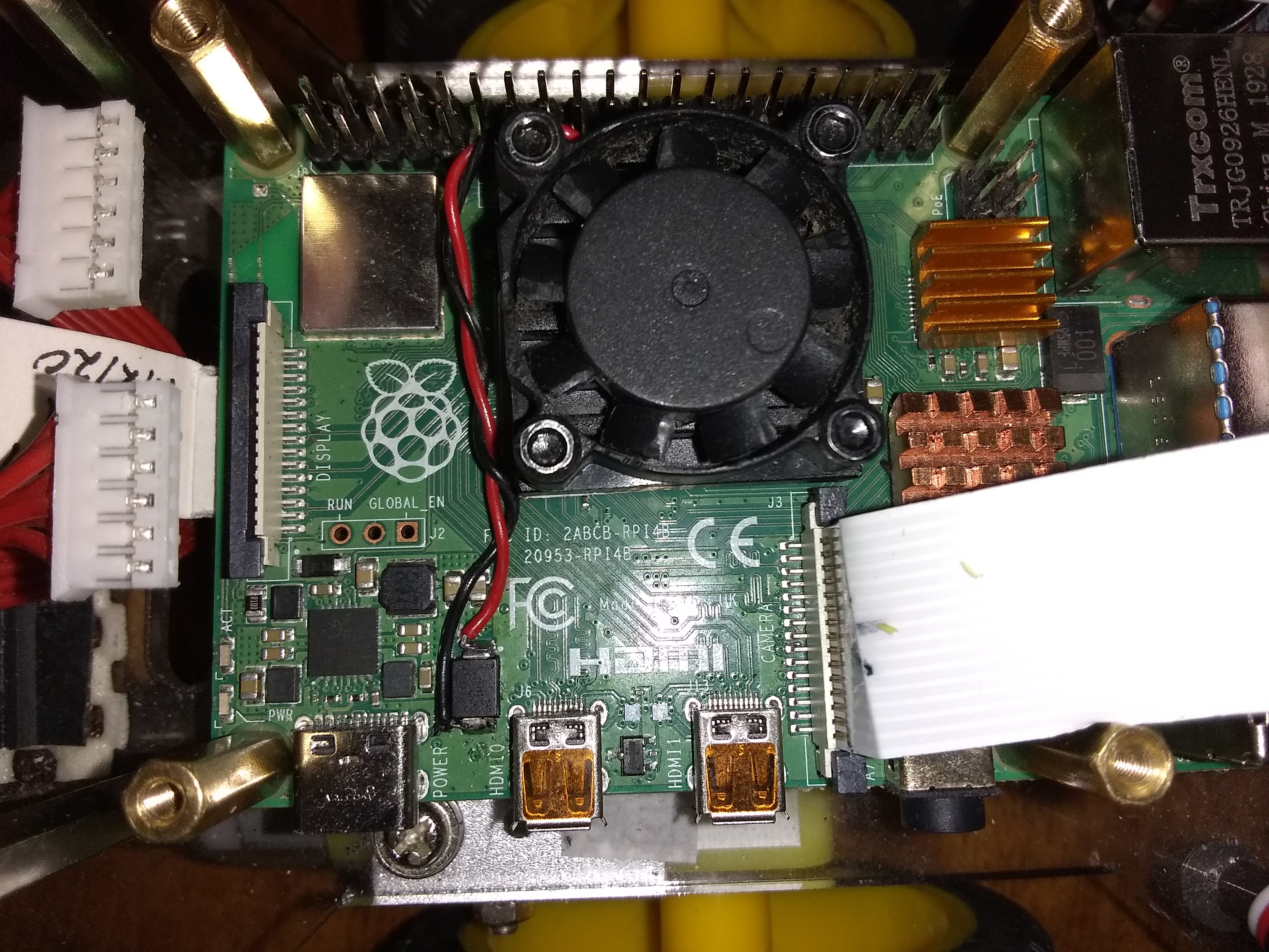
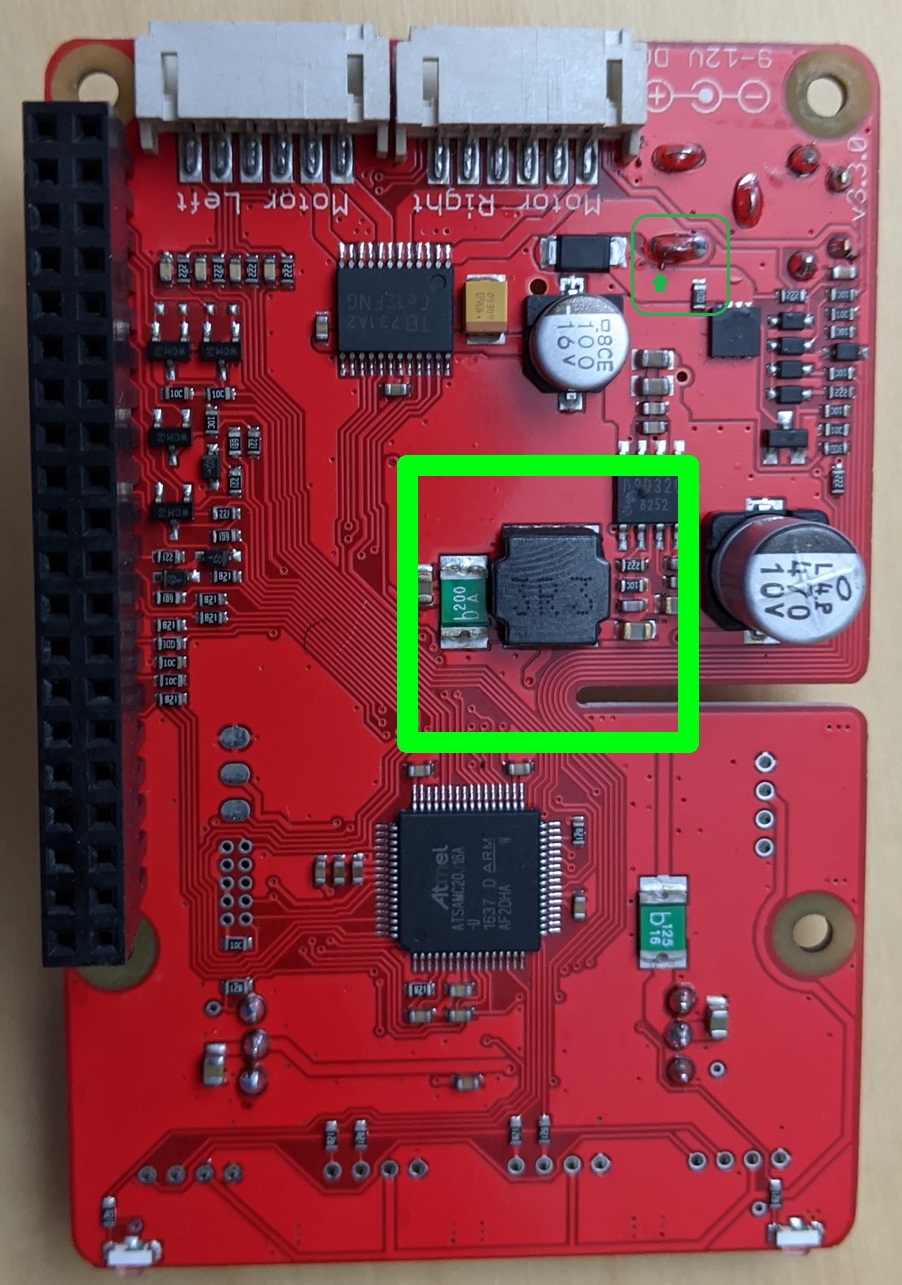
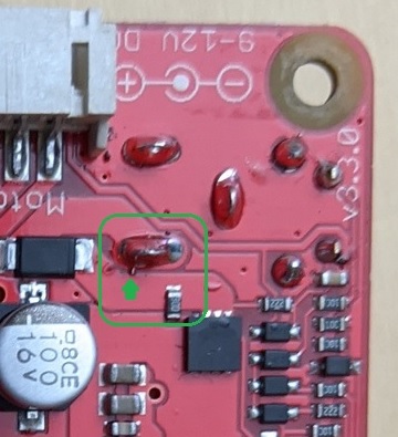
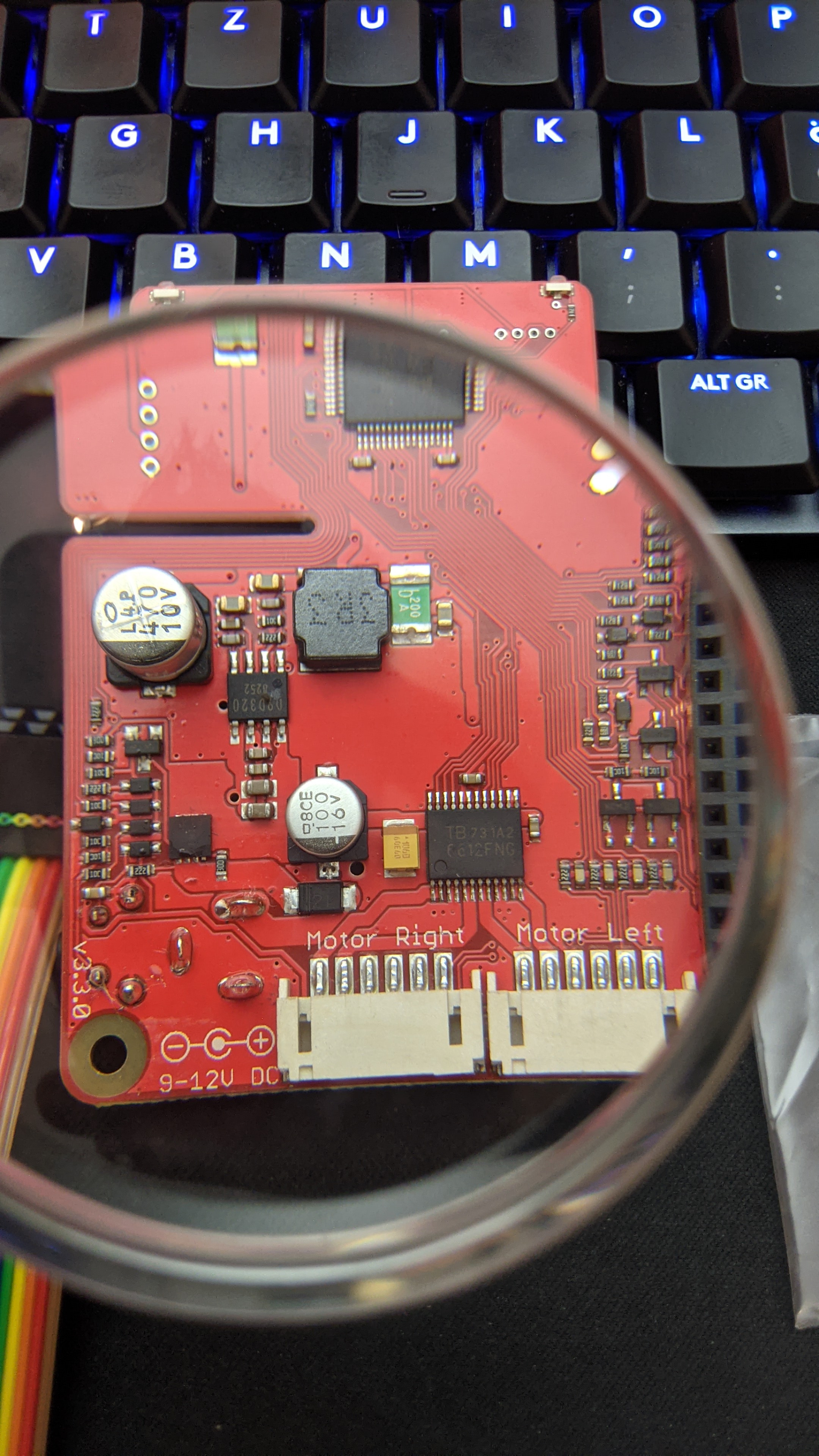
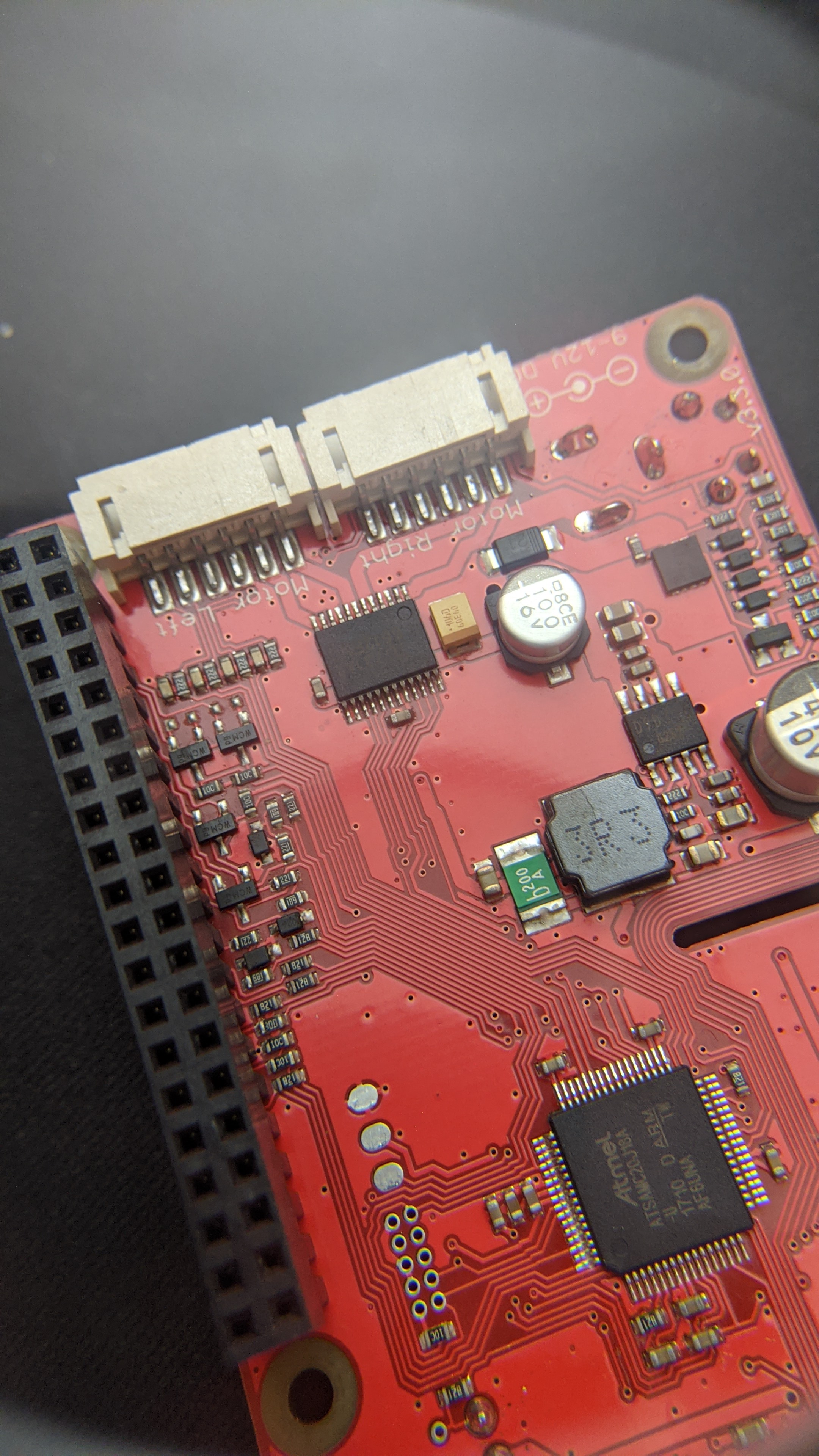
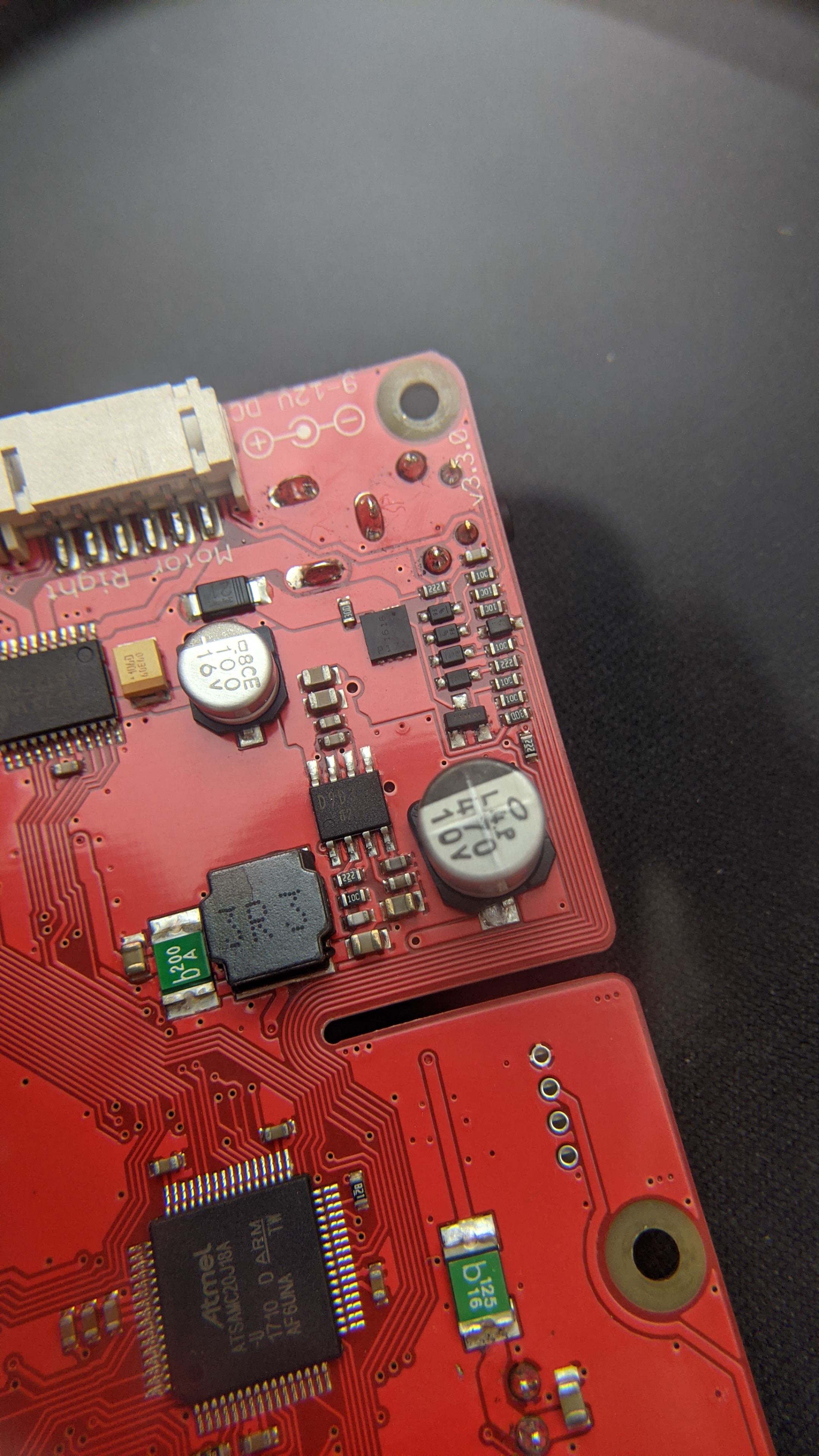
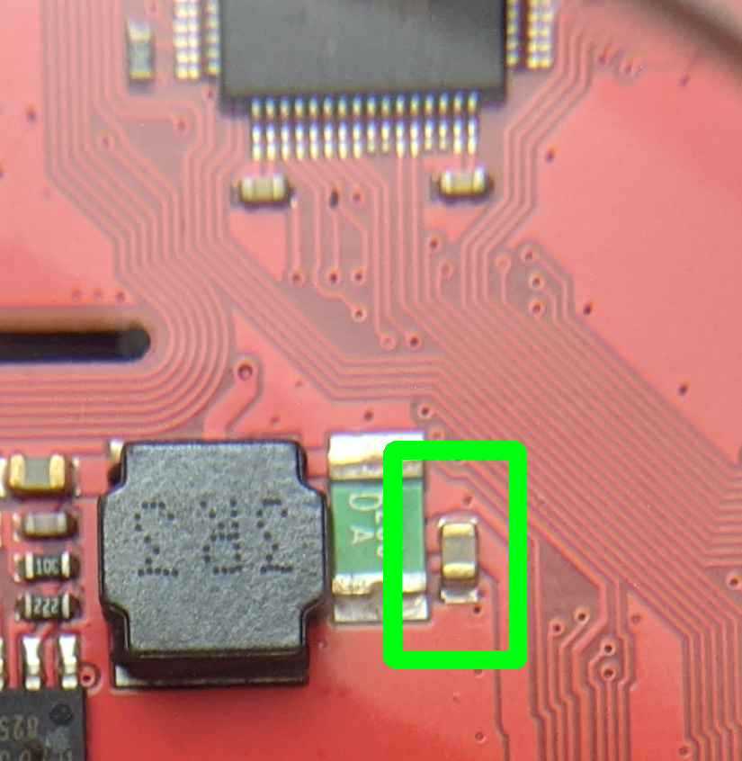
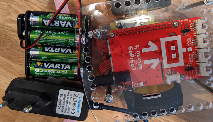
You have a “new” version GoPiGo3 controller board. The large electrolytic capacitor at the edge of the board near the camera cable slot used to be located between the large inductor coil labeled “3R3” and the smaller silver electrolytic capacitor to the right in that picture.

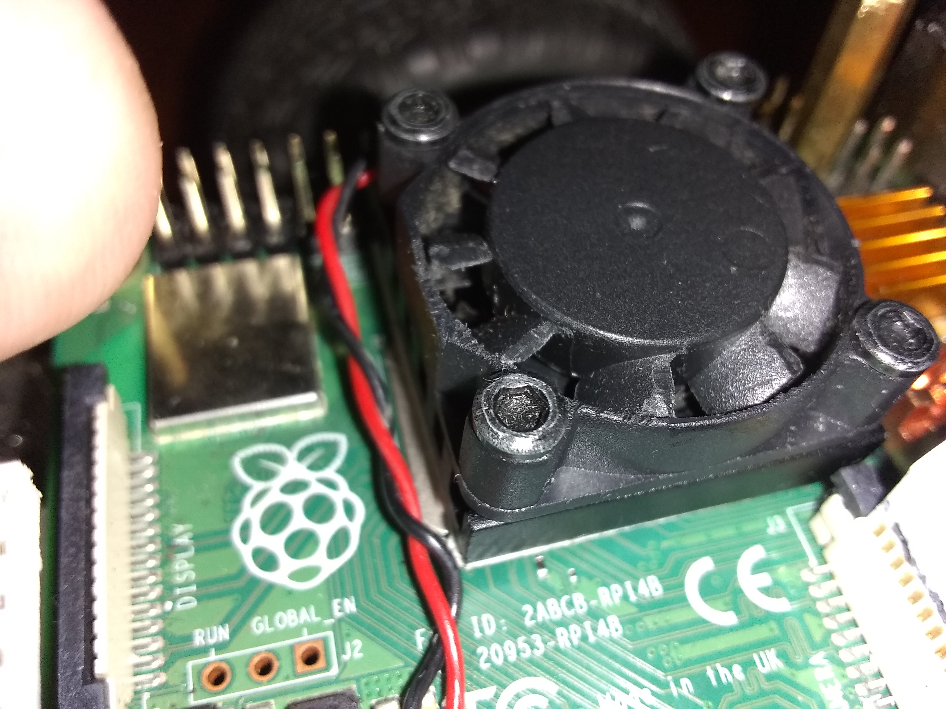
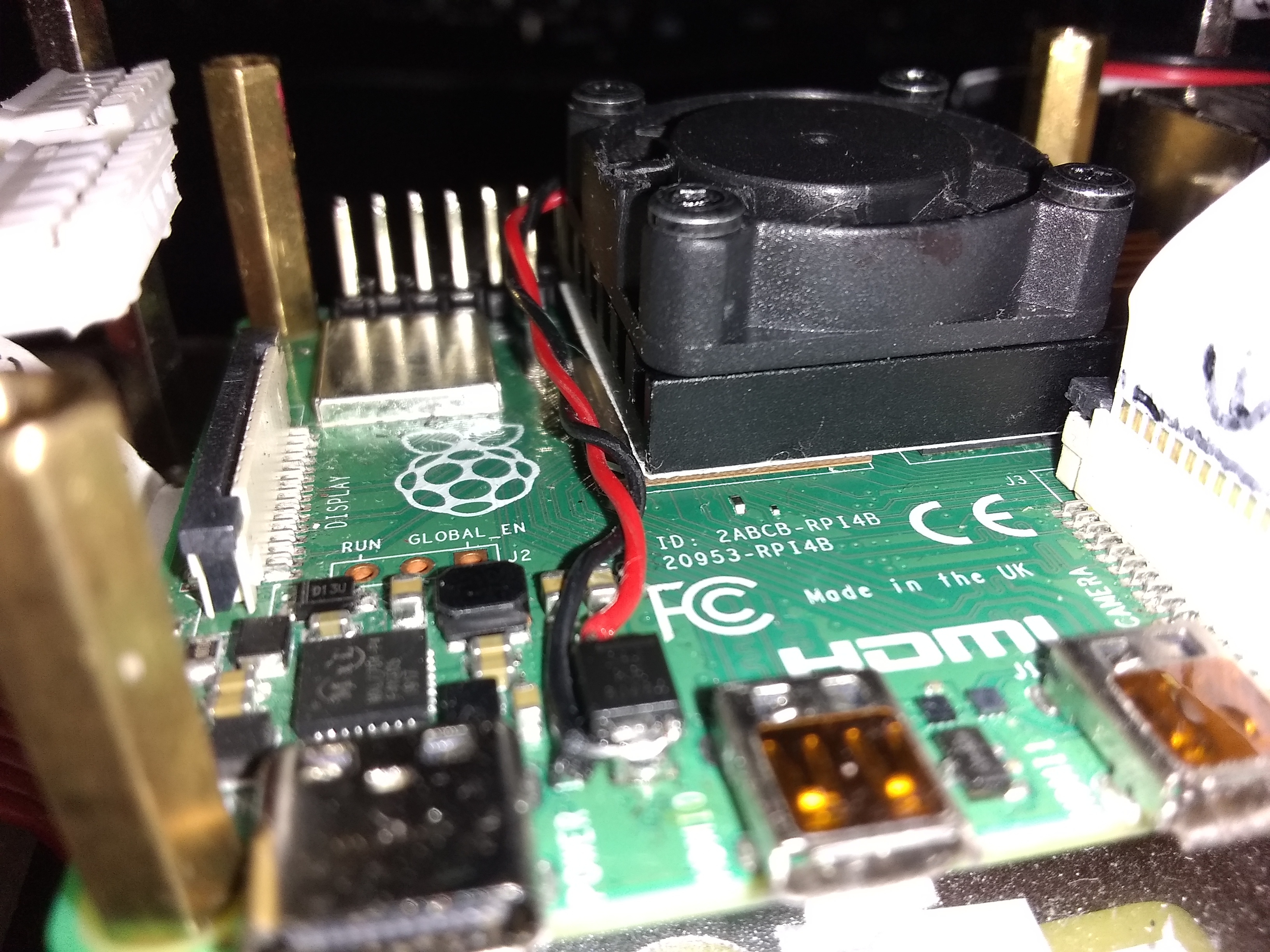
It was moved to make room for a heat-sink for the Pi-4. Note that if you try to use a heat-sink with a fan, the inductor will interfere with it. I solved that problem by trimming about 3mm from the tops of the fan blades.

the 10.23v that you get from the batteries is normal. Since NiMH batteries are rated at 1.2vDC each, these must be fully charged. (I have some Varta brand batteries too.)

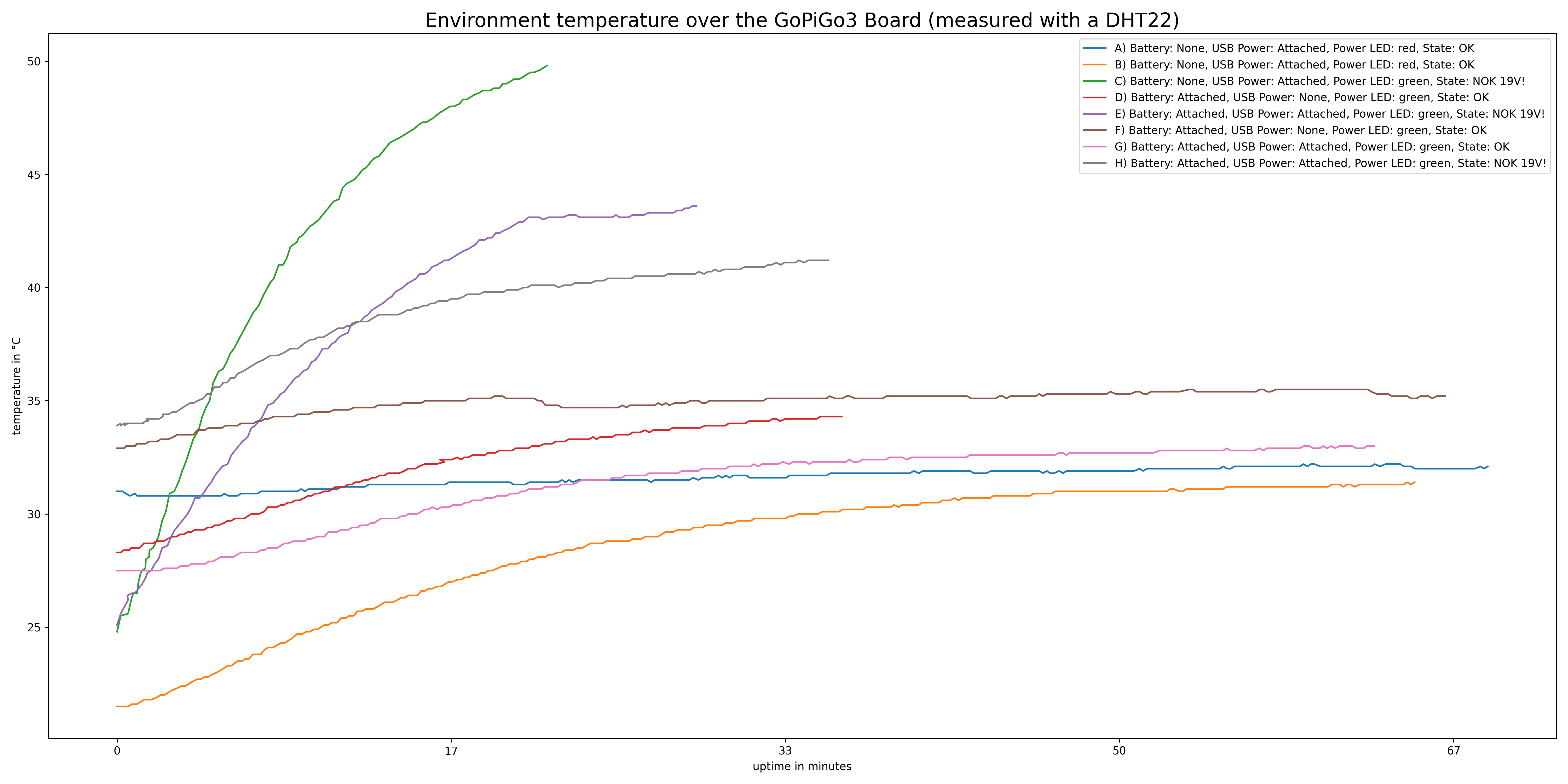
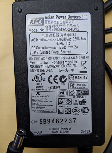
The artifact you noticed with the light and the presence and/or absence of the battery is normal. The “19.2” volts you see with both power supplies combined is an artifact of the fact that the GoPiGo board’s power sensing logic was not designed with the idea that power would be supplied both ways. On older boards it’s 14.something volts. I don’t have a new version GoPiGo3 board so I cannot compare.
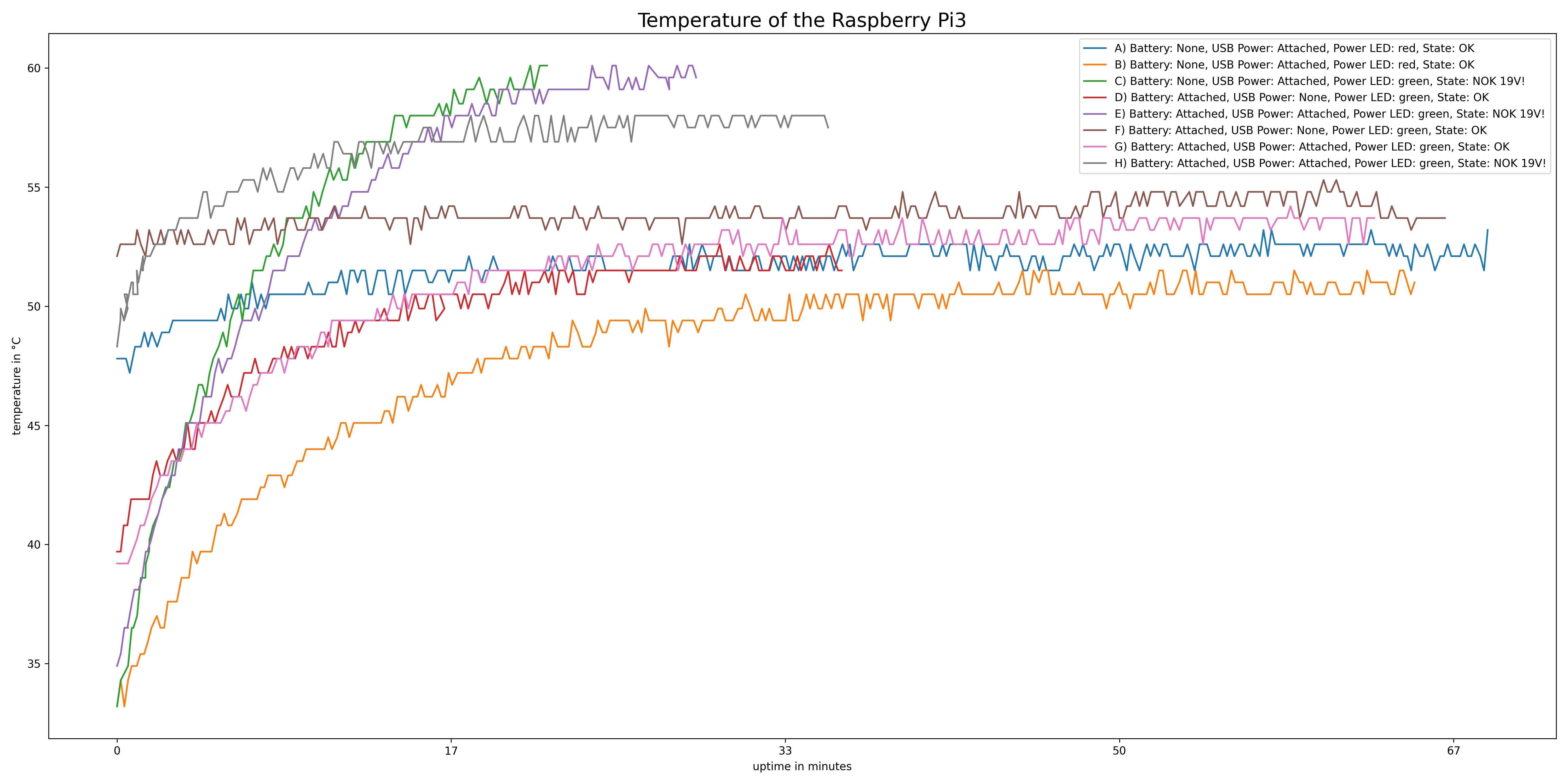
Regarding heating:
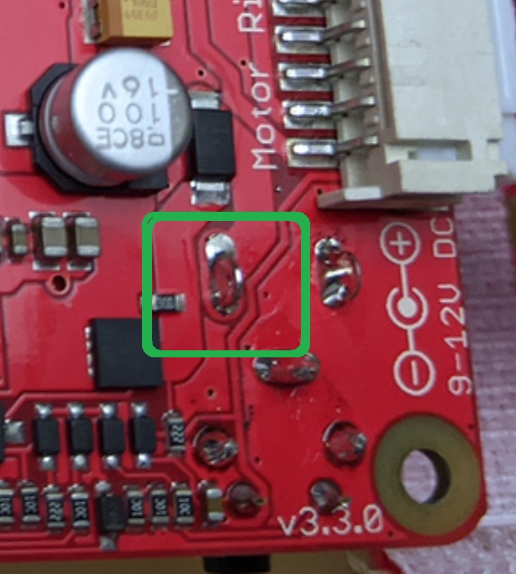
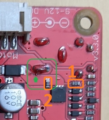
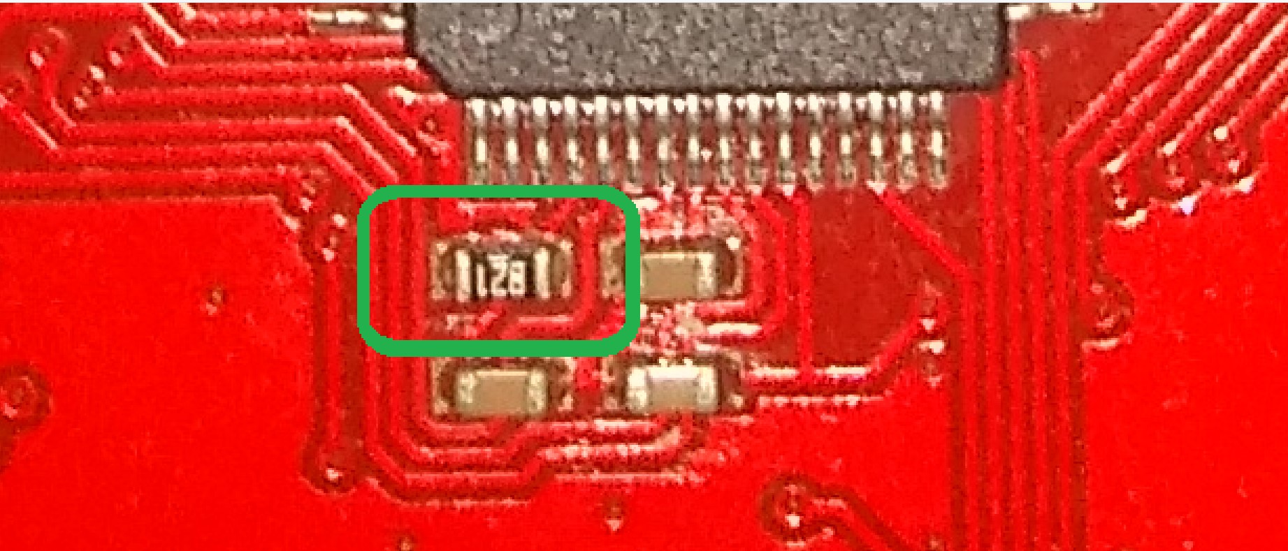
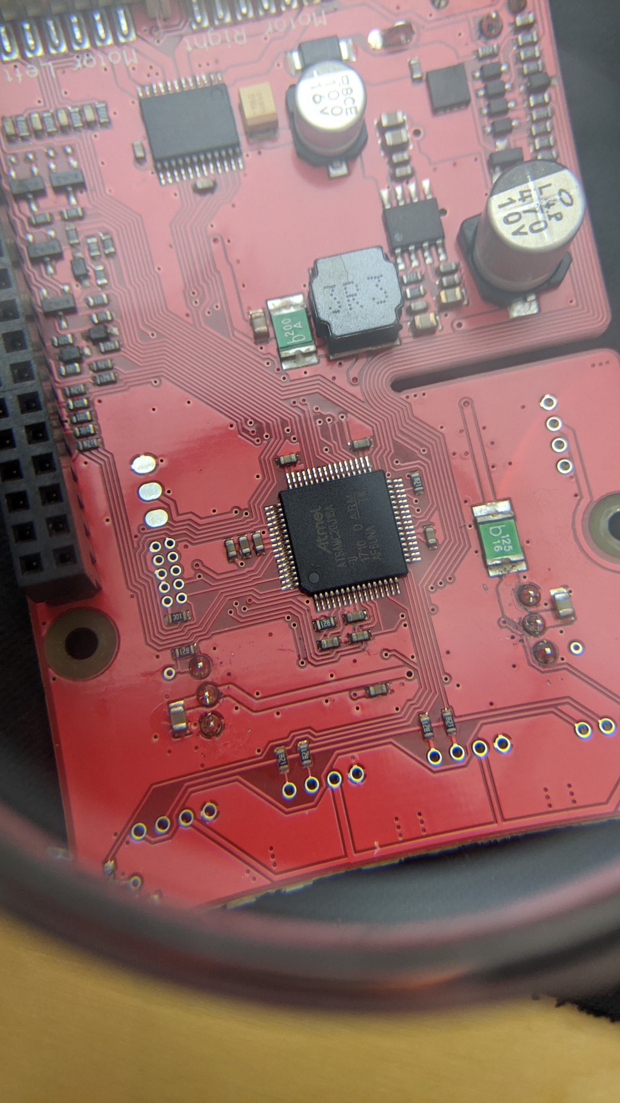
I cannot see any heat damage on the GoPiGo board, so I suspect that the heat is coming from the Raspberry Pi itself.

With the boards separated that way, and the Pi running from 5v power, what gets hot?

1 Like

I worked the whole day with the GoPiGo3. It worked well and I had no problems anymore.

My solution is to ALWAYS plug in FIRST the USB-Power-Supply to the raspberry. Then I can attach and remove the battery as often I need the motors.

But when detaching the USB-Power-Supply from the rasbperry pi, I shutdown first, remove the batteries and attach the USB-Power-Supply and start.

NEVER attach the USB-Power-Supply after the battery-pack and it works very well and no burned smell.

Thanks for all your inputs and help!

I sent an email to support@modrobotics.com, I’m curious what they will report back.

3 Likes

Interesting!

I never noticed that, and I’ve added and removed power supplies in random order many times.

Of course:

  1. I have the older style board. (though that should not make a difference)
  2. I am using a Pi-4 with a heat-sink and fan. Otherwise I get a “hot” smell too that comes from the Raspberry Pi.

If you decide to add a heat-sink and fan assembly to your Pi, let me know and I’ll send pictures describing how I did it.

1 Like

@jimrh I need the GoPiGo for a Machine Learning project and I would like to use a Pi4 in the future for more computing power (maybe I need another power source with more capacity too?).
I would be very interested in which heat-sink and fan you are using and how it is installed.

2 Likes

Things are a bit busy, I’ll try to get you some pictures in a day or two.

1 Like

Here are the pictures I promised:

This is the picture of my Pi-4 with the heat-sink and fan installed.
(Note that I did the same thing for my Pi-3)

Two things to note:

  1. The two wires are attached directly to the 5v reverse-voltage protection diode. (red wire/+ at the top)
    Advantages:
    a. It has direct access to un-buffered 5v DC.
    b. It doesn’t use up any GPIO pins.
    Disadvantages:
    a. It’s always running whenever the power is on, even if the board itself is not running.
    b. There’s no dynamic speed control.
    c. There’s no tachometer feedback to detect fan stall/failure.
    Note that these disadvantages - at least to me - are of trivial importance compared to the advantages in enhanced cooling, particularly the part about not using up any GPIO pins or i2c addresses.

  2. There is a (relatively) large IC directly above the power connector in the lower left.
    This is the power control/monitoring IC and it also gets quite hot according to the Pi-3/Pi-4 heat maps. Eventually I plan to cut a small piece out of another Pi heat-sink and attach it to the top of this chip.

Here are additional pictures of the heat-sink’s fan. Note that I have cut the tips of the fan blades a millimeter or so below the top edge of the fan’s shell. This is important because many fans actually “lift” slightly, floating on a magnetic field like a MAGLEV train. This causes the tips of the fan blades to rise above the outer shell.


This is another view, showing how the fan-blade tips are cut slightly below the edge of the fan’s outer shell.

The amount to remove should be determined by experiment. Trim them, place the board back on the Pi, fasten two screws on diagonally opposite corners, and power it up. (you don’t need to have a SD card installed, in fact it’s better to NOT have any kind of boot-device connected.)

Later on, if there’s sufficient interest, I will post pictures of how I installed an Adafruit Real Time Clock module to the bottom of the board with some ribbon cable.

Let me know if you need anything else.

1 Like

Hey woody123,

It looks like we’ve made some progress on here! I had sent you an email on Friday the 13th from our helpdesk. Please let me know if you didn’t receive it! Don’t forget to check any spam filters you might have active.

Talk with you soon,

1 Like

Any chance you can, at the very least, summarize this for the benefit of the rest of us?

Thanks!

This shouldn’t be the issue, as the GPG board is designed to handle both power sources at the same time. We suspect @woody123’s power supply to the Raspberry Pi is outside our recommended norms, but haven’t had a chance to test it.

2 Likes

Would not surprise me.

He’s using an Asiatic supply of a kind that I have too. It’s well worth testing both the output voltage and the ripple. (assuming you have a 'scope), as either or both can be, (shall we say), “interesting”.

Some of them say “12v”, but it appears that the “12v” is the nominal voltage under a relatively significant load. Open-circuit, or under light load, they can both have a higher-than-rated voltage and non-trivial ripple.

Another possibility is that he’s using a Pi-3. If he has inadequate heat-sinking, and/or inadequate air-flow, the board will get hot and smell hot. @cyclicalobsessive’s little test script is a valuable tool here as it allows you to monitor the temp of the board. In my case, (using a Pi-4), the presence of a fan drops the CPU temp by at least 20° Celsius, which can be the difference between a hot, burning smell or not and throttling or not.

In my case, (using a Pi-4), running his script with the fan running vs the fan stalled with a small screwdriver, made a significant difference in the temp of the board.

Suggestion:
If the GoPiGo O/S and/or firmware can keep track of the CPU temp, and cause the power lamp to either change color, or flash in a particular way, when the temp rises/CPU throttles, (or even both), that would be a Good Thing.

Nicole could add a block/construct to the Blockly programming environment that allows the measure of the CPU temp. (If it does not exist already, I haven’t checked yet.)

2 Likes

@mitch.kremm I sent a response to you - it contains mostly the same like what I wrote in this thread.

@jimrh I don’t use the asiatic supply https://forum.dexterindustries.com/uploads/default/optimized/2X/c/c63bd9ff78e591f6079a6485ba56d31ec3a5a4b9_2_367x499.jpeg anymore, I tested that only once and because it generated a high frequency tone, I never used it. The power supply I use is only the one for the raspberry pi like the one in the picture https://forum.dexterindustries.com/uploads/default/optimized/2X/5/58fda7c0170f7eb32834c155e22e528d3cc33699_2_690x397.jpeg.

I’m a little bit surprised only I can see a voltage of 19V with the following steps:

  1. Plug in the usb-power-adapter, the raspberry pi starts and I can connect to it (power light is red)
  2. Executing the script shows Battery voltage : 4.608
  3. Plug in the Battery pack, Battery voltage shows 9.08 (power light changed to green)
  4. Remove the Battery pack, Battery voltage: 4.608 (power light changed to red)
  5. Plug in the Battery pack: 9.08 (power light changed to green)
  6. Turn off the usb-power-adapter plugged in the raspberry pi: 9.08
  7. Turn on the usb-power-adapter plugged in the raspberry pi: 19.591!!!
  8. Remove the battery pack: 19.591!!! (The power light is still green!)

I can reproduce this behavior all the time and then it seems (imho) that it heats up more than normal.

I apologize very much for the big wave my entry is making :upside_down_face:. I have received a second GoPiGo3 with Raspberry Pi and will see if I can reproduce the same effect with the steps above.

But now apart from the heat that is produced (which unfortunately I cannot measure exactly at the moment and is just my feeling!!!), should the script “all_test.sh” never show such a high battery voltage of 19V?

3 Likes

I have learned to trust my gut “feelings” a lot more than a lot of (supposedly) expert texts. Science is only as good as its data - and it’s not uncommon for the data to be “interesting”.

The “19” volt reading is an artifact of using both supplies at the same time. I do not know exactly why this happens, but I would suspect that the presence of the Raspberry Pi adapter causes the “reference” voltage used to measure the battery to change. That would cause the readings to change dramatically.

In any event, the change in measured battery voltage is a result of the two power supplies being present at the same time, and not an actual measurement of the true battery voltage. (at least as far as I know as I have never done any significant research on this.)

Does your meter have a thermocouple input?
Have you tried running cyclicalobsessive’s script?

It would be very interesting to see what the temperature of the CPU does when either one, or both, supplies are attached.

1 Like

That might actually be a fun block to have!

2 Likes

To substantiate my feelings and to back them up with facts, I took a DHT22, glued it under the cover plate but above the GoPiGo3 board and carried out some measurements.

Here is a picture of the installation:

And here are my results:

You can clearly see that when the whole thing gets into a state in which 18-19V are reported, the heat development is greater than usual.

I switched off the Raspberry pi as soon as it starts to throttle, here an example of the last entry in the data for the case C):
18:31:24 up 22 min, 3 users, load average: 0.19, 0.18, 0.11 | temp=60.1'C | volt=1.3438V | frequency(45)=1400000000 | throttled=0x80000 | Temp=49.8*; Humidity=28.4%; | Battery voltage: 19.557; 5v voltage: 4.921; Dexter Industries; GoPiGo3; ...; 3.x.x; 1.0.0; |

During the measurements nothing ran on the Raspberry Pi / GoPiGo, it just stood there and did nothing, except produce heat.

And to be sure that there is no problem with the usb-power-supply, I tested two of them:

And now for the other bad news: I received a second GoPiGo3 this week, exactly the same board (v3.3.0).
I have now tested whether this has the same behavior and unfortunately yes - even with that I sometimes have a status in which 18-19V is displayed and it is heating up.
To make matters worse, this board has now stopped working. I don’t know what happened, but there was a smell of burning and I immediately cut the power and removed the battery. If I now plug in the battery, nothing happens and the board can no longer be switched on. But if I put the board on a Raspberry Pi and feed the Raspberry Pi with a USB power adapter, the power LED flashes and the board seems to start. BUT after a few seconds a part on the board heats up so much that I switch it off again because it’s just too hot and I don’t know what’s going on. The part that heats up so much seems to be the one marked in green:

Now I have to ask the support what I can do and whether I can get the board replaced (or maybe both). I would also be happy if the support could check the board (maybe also my other one with the heat problem) - I don’t know what I could do wrong :frowning: :frowning: :frowning: or whether I just have bad luck. :frowning:

It’s a little bit frustrating because the product is very cool! I have chosen this robot for my semster thesis which should be finished in one month - but I lose a lot of time with the heating problem. :frowning:

I will now write to the support and hope they can help me out.

One last question: One last question: Nobody here has exactly the same board (v3.3.0) and the same problems?

3 Likes

This is extremely interesting.

Do you mean the large square shaped part labeled “3R3”?

That’s the power supply regulator filter inductor and there’s no real reason for that to get hot absent a drastic short circuit somewhere.

IC-1 is the power regulator IC. Does it get hot? How about the two big silver capacitors?

Frankly, without sitting down with you and looking at that with meters and tools, I honestly don’t know what to say.

Have you considered connecting the pi to the controller board with a 40-pin ribbon cable?

I hesitate to suggest this, and didn’t suggest it before, because it’s really easy to get the pins flipped and potentially fry both controller and pi.

If you are confident enough to try this, and carefully see what parts are getting hot, that would be very helpful.

Also, have you tried a different Pi?

One last thing I forgot to ask:

With the two halves assembled, have you looked for accidental points of contact between the two boards?

What if the two motors are disconnected from the controller?

Do you have anything else plugged in?

You really have my total attention with this!

I wish I could be there with you to help figure it out.

@jimrh I also wish very much you were here and could tell me what’s wrong here :slight_smile:

1 Like

I was examining your board with a bit of magnification and I noticed something potentially interesting that looks like a solder-splash across two power traces near the upper right of your picture.

Viz.:

Full size:

And a cut-away

Solder Splash-2

Does that exist on both boards? Is this board still working? If so, would you flick it off and see if that eliminates the problem?

For comparison, here’s a magnification of the original board pictures you showed me. You will notice a much better, and cleaner, soldering job done to that pin.


A couple of other things that confuse me:

Viz.:

Incorrect components

According to the schematic I have:

  • item #1 should be a diode, not a 22k resistor.
  • Item number 2 should be 200k, not what looks like 30 ohms. (“300” in resistor notation should read as 30x100, in other words, 30 ohms. The other, reading “222” should read as 22x102, in other words 2200 or 2.2k - the last digit being the “multiplier”, or the number of zeros to append to the two numbers that represent the value.)
    Note also that my PCB, which is an older version GoPiGo-3 board has the same 30 ohm resistor there.
     

For comparison, look at the 820 ohm current limiting resistor leading to pin-4 of the Atmel controller chip, (5v Vref). It is labeled “821” which equates to “820” ohms.


My schematic, which is marked as the GoPiGo 3.2.0 version, shows completely different values for a lot of the components in the power supply and power management sections.

Note that, aside from the resistor in place of the diode, your boards components look just like mine, except for the placement of CP14, the very large silver electrolytic capacitor, which on your PCB was moved to the edge of the board.

Here’s that side of mine.

You will notice that I have moved CP14 to more closely match the location of it on the new PCB so that it will fit the heatsink and fan on the Pi-4.

@cleoqc
@mitch.kremm

Have there been any electrical/component changes in the GoPiGo PCB that aren’t reflected in my version 3.2.0 schematic?

How difficult would it be to ship a latest-rev controller board to Moscow Russia? This might need a bit of closer examination of the hardware.

1 Like

I checked the soldering and cleaned that, but it did not help.

Pictures of the dead board:

And the working (apart from the heat problem when not only using the battery pack):

I found a cable and could run with boards separated. The 3R3 is not the one heating up on the dead board, it’s in this area:


When I check it with my fingers, it’s one of the two next to the 3R3, would say the little one (in the green box). And a few seconds it’s normal and then it heats up very quickly. If I know what could happen I would let it run… i have no idea about it and i’m a bit scared. :slight_smile:

1 Like

Is it the bigger green part or the tiny brown one?

Can you get me a nice, clear, square-on picture of the other side?

Do you have a can of compressed air like "Dust Off?

Here’s a trick:

Hold the can upside down and spray the cold liquid on the board all over that area. Do it a couple of times. Get it nice and frozen. (Be careful of the IC’s)

Then turn it on with both supplies and see what warms up first.

1 Like

@jimrh Here a picture from the other side (hope it’s clear enough - aks if you need a cleaner picture of something else or a sector of it):

I have no can of compressed air and the picture I’ve send is from the dead board. I would like not to lose my warranty at the moment (for both boards). The other board works (with batteries only) and I hope I don’t lose that too because I have to go forward with my semester thesis - no experiments on the board that runs actually until I have an alternative. :slight_smile: But if I have an alternative/solution, I would be very happy to give you the informations and do further investigations.

I have contact with the support (@mitch.kremm) and hope they can help me out somehow.

I thought I could order a new one from a shop here in Switzerland, but if they send me the exact same version (v3.3.0) again, I don’t know if I would have the same problems.

Thanks for your help!

2 Likes