The most you were able to get from the guy that designed that part of the bot:
You go guy! Now we’re going to get some answers.
The most you were able to get from the guy that designed that part of the bot:
You go guy! Now we’re going to get some answers.
There’s also a purple colour that can show up. This means the Pi is shutting down but there’s still power going.
Do you know what voltages trigger what colors?
I do not know, but I suspect that there may need to be a firmware update to account for the different charge slope and endpoint voltage with lithium batteries.
Here is a preliminary “dry fit”, (to make sure everything fits in the box), view.
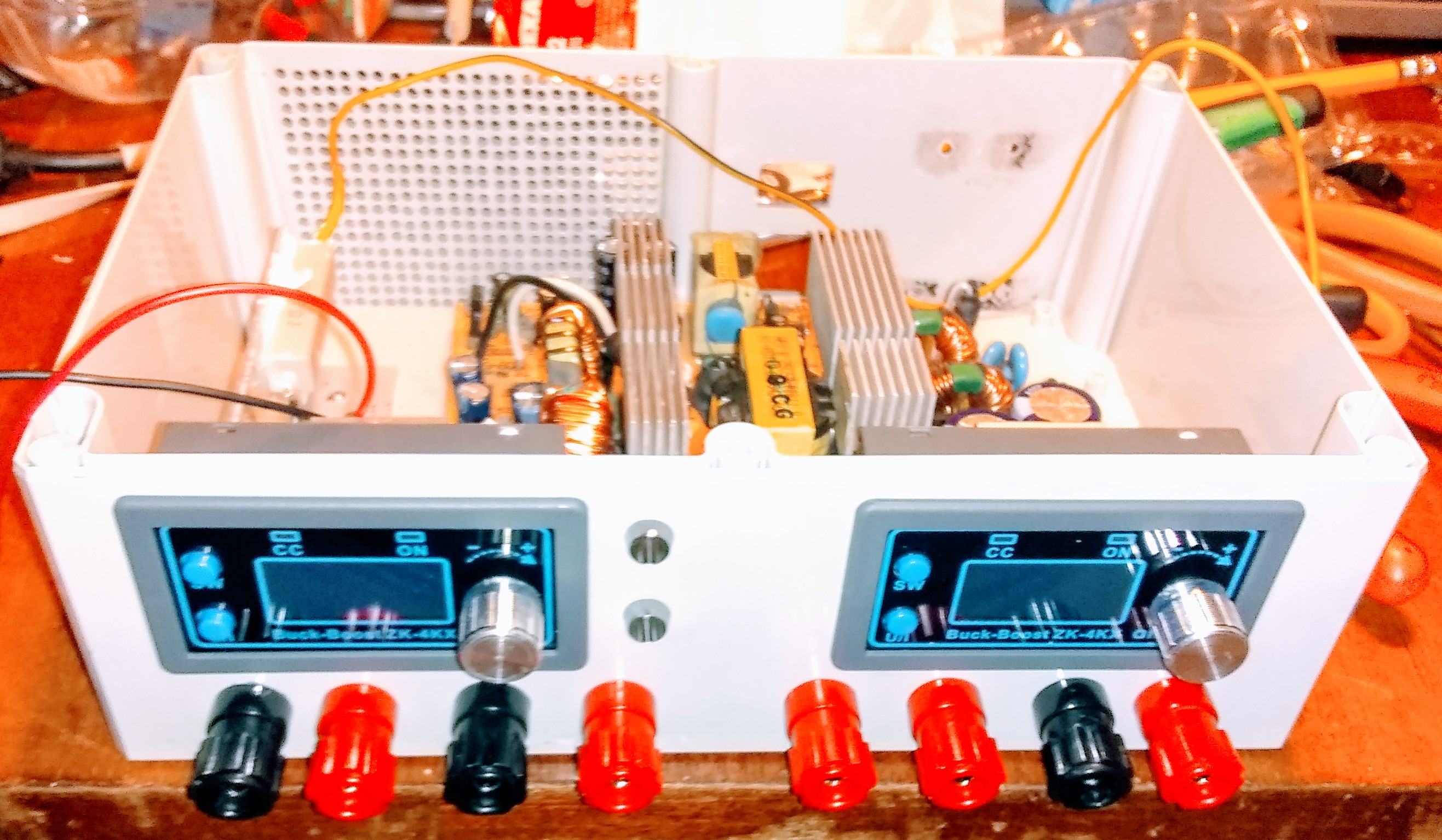
This is the (mostly) assembled appearance without the lid and fan.
You can see two ZK-4KX zero to thirty buck-boost adapters that I will run off of the high-current +12 line. (They max out at 4 amps)
This will give me a dual variable output.
I am also going to bring out the +12, +5, +3.3, and -12 volt lines to banana jacks on the front panel.
My wife thinks I’m absolutely crazy, but using the innards of a Cooler Master 450w supply gives me excellent regulation, low noise, lots of current to play with, and I can’t touch a dual output supply like this for less than a couple of grand USD.
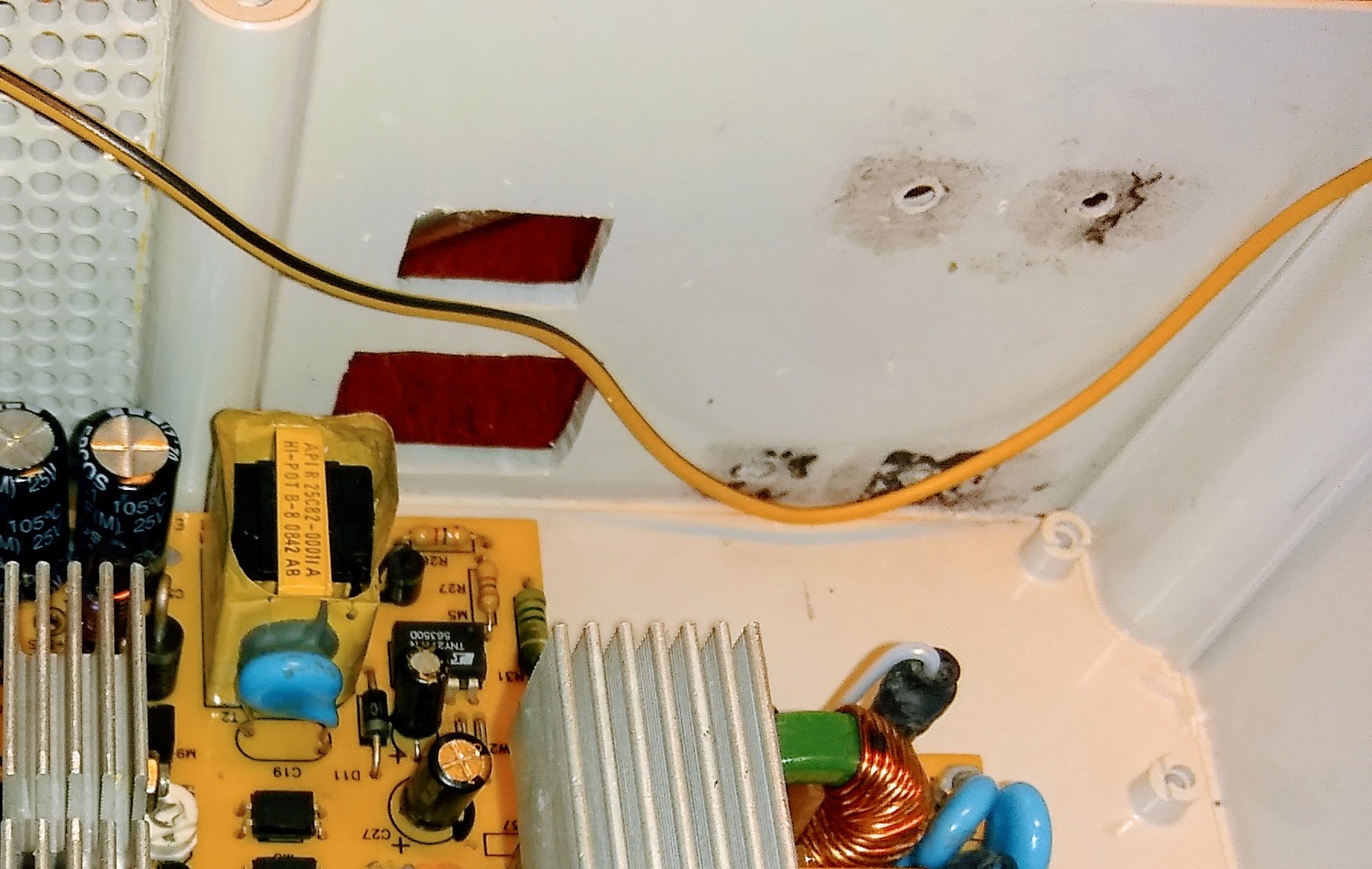
This is a view of the inside. You can see the PCB from the ATX supply and the load resistors for the +12 and +5 volt lines. (You need this to keep the supply active and to reduce switching noise.)
I attached them to the heat sink with special high-temperature heat-sink glue like they use to glue processor heat sinks.
If you look directly above the main heat sink, you will notice two big electrolytic capacitors. They had gone bad so the supply had been removed from a working system.
Two inexpensive capacitors later and I have an expensive supply working 100%.
I still need to figure out how to label the thing and paint it.
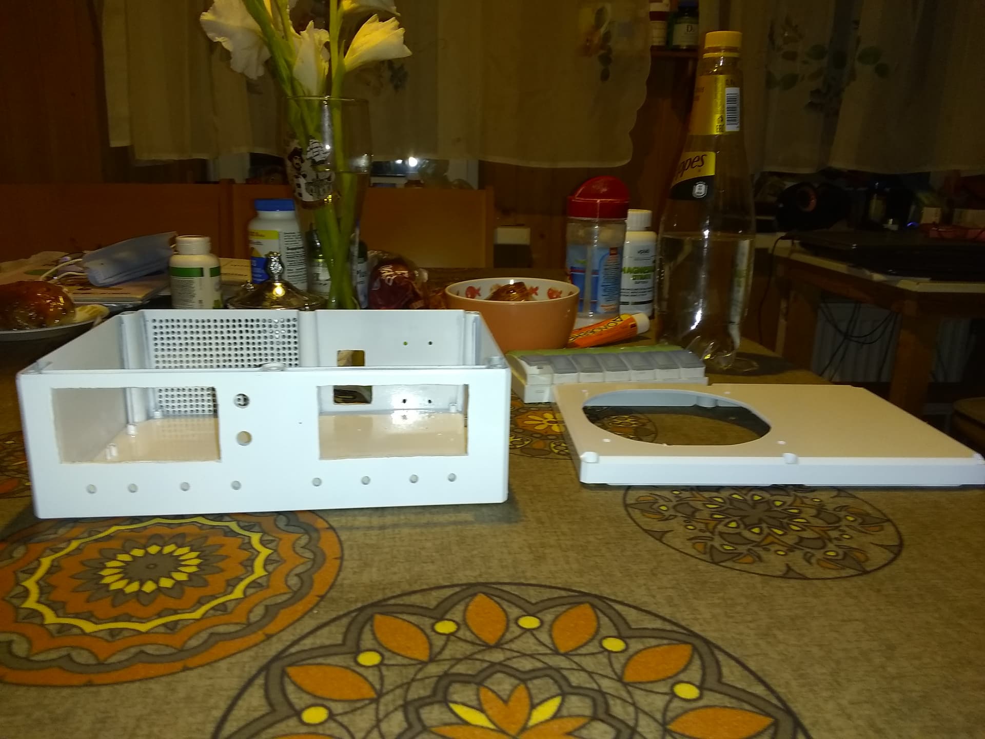
And this is WHY you “dry fit”:
The large rectangular hole is for the AC power connector. The four holes are for the main switching inductor, (shown in the second picture.) It’s huge so it can handle the power necessary without saturating and burning up.
Neither will fit behind the main PCB (though I measured carefully) so the PCB will have to move about an inch to the left.
Rats!
@cyclicalobsessive’s posting about Carl’s third birthday,
. . . reminded me you folks are due for an update.
The current effort is the bench power supply I am working on.
The electrical disassembly and repair of the base power supply PCB is done.
After several iterations, the mechanical layout, drilling, and dry-fitting is done.
The current step is paint-and-label.
Here is the painted case.
And here are the front-panel binding posts. Each voltage has a unique color based on the ATX cabling color-codes.
Right now the big issue is “drying time” since I don’t have a paint drying oven and Svetlana absolutely refuses to allow me to appropriate hers for the task.
As a result, I paint something, wait hours, paint again and wait overnight, rinse and repeat.
I can’t wait to be able to show you the completed project.
Then I can get back to more important things like the battery and the robot.
Another annoying delay:
I found transparent address labels, (tiny ones - 40 per A4 sheet), that come from St. Petersburg, (Leningrad), and they won’t arrive until the end of the week.
That’s roughly the distance from Miami to St. Petersburg, Florida. (i.e. the length of the peninsula, driving.)
So much for Amazon Prime! 
Make that “I wish we had the equivalent of Amazon Prime here!” 

The idea is to print the various labels and legends on them, cut to size, apply, and then coat with clear lacquer so that, (hopefully), they blend in and look like they are printed on the panel.
Just in case you were interested. . .
These are the colors I am talking about.
Red: +5
Yellow: +12
Orange: +3.5
Blue: -12
Green: Variable voltage outputs (two sets)
Black: “Ground” return for all voltages.
Note that green is not a “standard” ATX voltage color, but then again the ATX power supply standard doesn’t have a variable voltage output either.
The supply I am basing this on is a more modern “version 2” supply so there is no -5 voltage. I can derive that whenever I need it.
PS “on”, (green) is shorted to ground to enable all the primary voltages. +5v standby is always on whenever the supply has power.
The two LED’s on the front panel are for +5 standby, (supply ready - green), and PS OK (supply active - red).
PS OK is actually an interesting output. Before it is asserted, PS ON has to be grounded and various voltages have to be within specified limits.
If I can find a small enough toggle/push-button switch, I will place that on the front panel to activate the PS ON connection to apply power to the front panel connectors.
If anyone else is interested, I will publish a schematic for this project.
uve got it worked out great.
Update:
Today I received a box of transparent Avery ink-jet labels to make descriptive labels and legends.
I then spent all day printing labels and trying to make them fit on the box. (And not slant sideways which they always seem to do.)
The result is this:
The labels aren’t THAT great, but compared to the alternatives, (laser printed decals or silk-screening), this will have to do.
I wait a few days for the clear-coat to cure, then I assemble and test.
Wow - 3.3v at 20A … I’ve been wrong thinking of 3.3v devices as “low power stuff”
That’s a serious power deliverin’ juice box.
No. You are not wrong.
20 amps at 3.3 volts is 66 watts, less than a single CPU draws.
The +12 rail can actually source almost exactly 40 amps! (I rounded to thirty so that some idiot wouldn’t grab my box to jump-start a car! And to provide headroom for the two variable power modules that max at four amps each.)
40 amps at 12 volts is 480 watts!
The five volt rail can also source 20 amps, which is another hundred watts.
Of course, even a BRUTE power supply won’t be supplying max power from all the power rails, but what IS included is enough “headroom” for power spikes when the CPU/GPU goes bonkers running Prime-95, or you spin up four or five big hard drives at the same time. (Or, you have your flight simulator running four monitors at 4k resolution with max detail set. )
Looking forward to seeing the final product.
/K
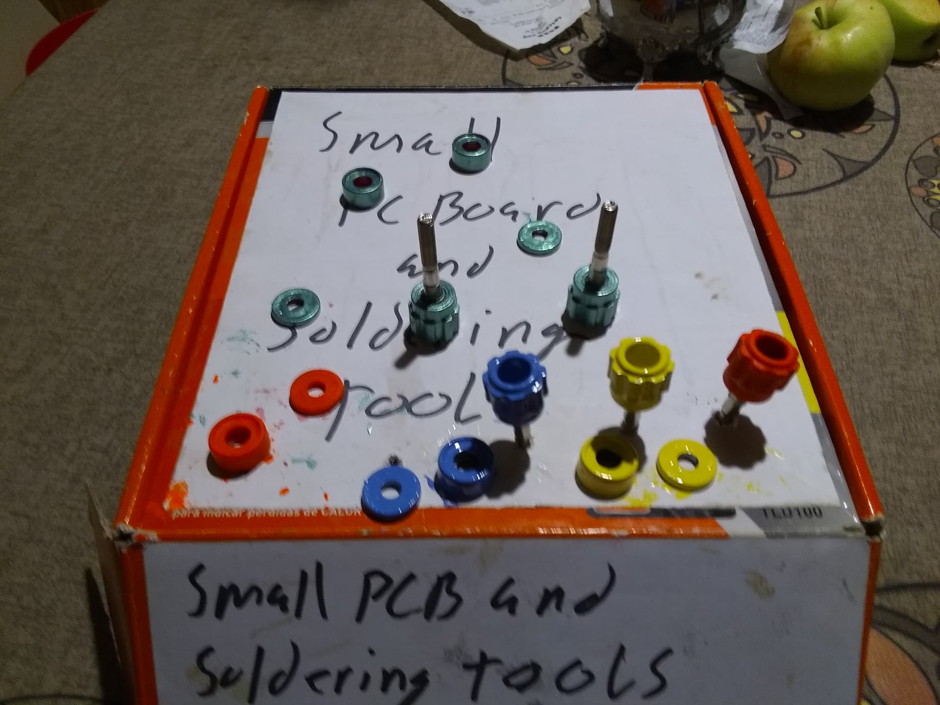
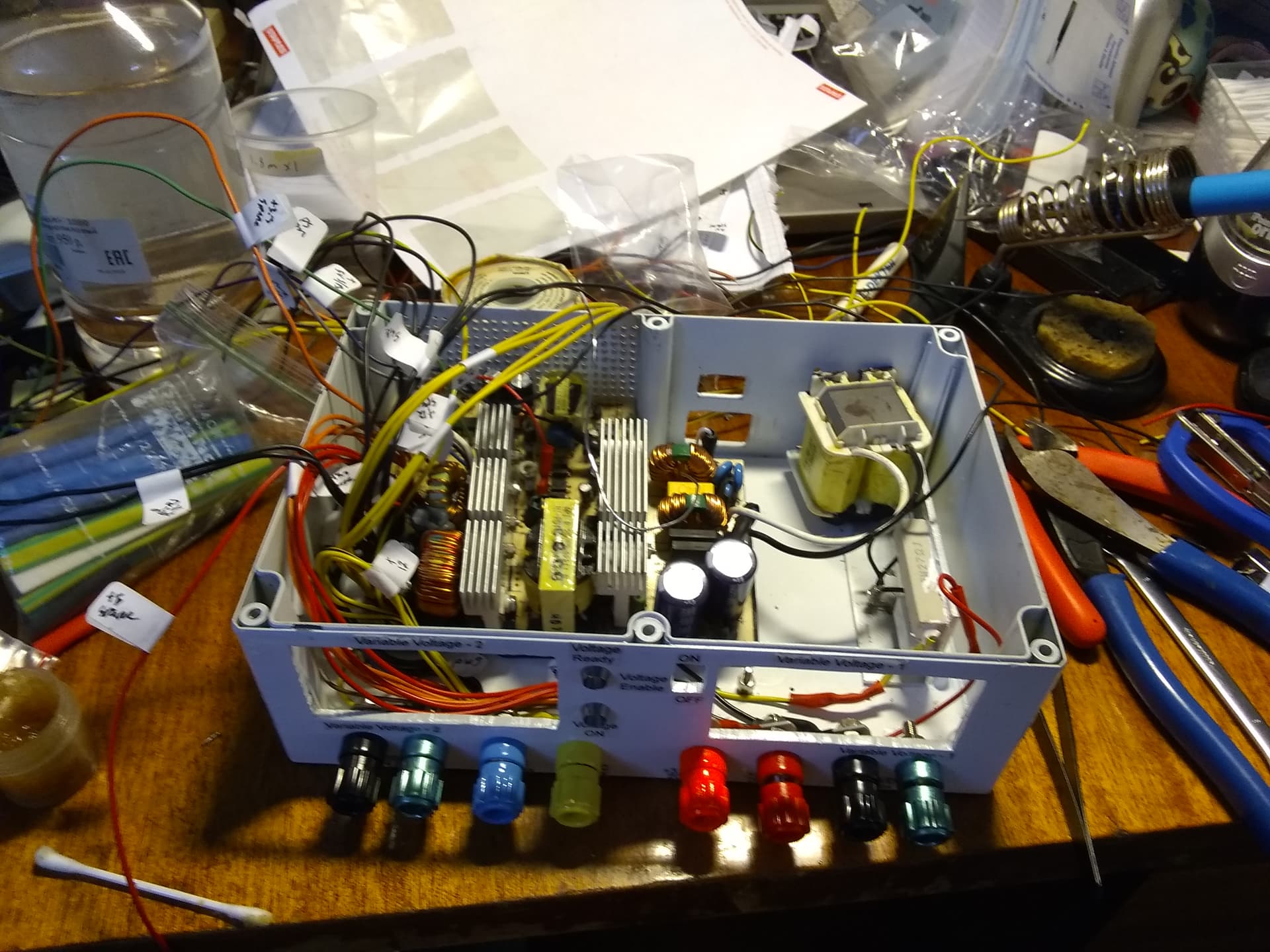
Another picture:
A rat’s nest. Parts and wires everywhere. I’m thinking “How did I imagine I’d get everything in the box?!!” and “How do I hold a LED with one hand, a resistor with the other hand, and then pray for a THIRD and FOURTH hand to hold the soldering iron and solder?!”
[NB You use a little gizmatch with a cross beam and two alligator clips.]
I am posting this for the benefit of @cyclicalobsessive and @KeithW so they see that when things look like they can’t get any worse. . . .
. . . Victory is just around the corner!
Where’s the fan going? Over that power resistor?
I see it now. Its a biggie! Is it external or internal?
That looks like a plastic box. Did you coat the inside with metallic paint to limit EMI (Electro-Magnetic Interference)?
Actually, that’s two of them, [power resistors] - one for the 12v load, (the one you see), and one for the 5v load.
Surprisingly, the both get rather hot, so they’re on a heat sink.
The fan was originally going to go over the main power supply circuit board, but the fan bumps into the power module. I could make a cut-out in the fan shroud to accommodate it, but I’d have to remove an important support for the fan motor.
Reversing the location allowed me to make the cut-out without removing any important structural elements.
So. . .
Now it goes over the resistors and then flows to the PC board. (Hopefully!)
Frankly when I saw what a rat’s nest it is at this stage in the construction, it reminded me of the two of you struggling with your LIDARs and trying to make ROS play nice in the sandbox.
The fan is internal, with a wire screen. That’s why it bumped into the power modules.
IMHO an external fan makes it look like a hack-job.
Shouldn’t the flow be in from the back panel grill, across the honkin’ PS, across the power resistors, and out via the fan?
Maybe.
The original design had the fan provide positive pressure, blowing into the case across the PCB.
My own, admittedly limited, experience has showed me that positive pressure ventilation is always more efficient.
The only time I use a negative pressure fan is at the other end of a complex internal air-flow driven by a positive pressure fan, to help keep the air moving and prevent dead-spots in the airflow.
Complex computer cases get multiple fans, especially if high-RPM, high power HDD’s are being used. Then each HDD gets its own private fan and the entire HDD cage gets a fan or two.
Heat is most definitely NOT your friend!
Jeez!
Next you will want me to get FCC, CA, and TÜV certification?
Nope. Not a serious concern right now.
If the FCC were to come knocking on my door in Moscow Russia, EMI is the LEAST of my concerns!!
I tried that by accident. I originally wanted a light federal grey color and I found what looked exactly like what I wanted. Turns out that it was a zinc primer and didn’t adhere worth poop. I guess metallic/metalized paint doesn’t stick to that kind of plastic.
P.S.
I did keep all the mains power filtering and grounding as power line trash IS a concern. I want to avoid it and I don’t want to add anything else to an already sucky power line.